|
|
|
|
содержание ..
1
2
3
4
5
6
7
8 ..
Aprilia scooter (manual) -
part 7
BODYWORK
-
BODYWORK

-
Light unit
-
Front cover
-
Left mirror
-
Rear brake lever
-
Rear brake master cylinder
-
Left switch
-
Glove compartment
-
Legshield
-
Central tunnel
-
Saddle lock
-
Luggage rack
-
Tail
-
Tail light
-
Number plate holder
-
Mudguard
-
Air filter
-
Transmission oil level
-
Engine oil level
-
Centre stand
-
Passenger footrests
-
Side stand
-
Rider footrests
-
Warning horn
-
Front brake calliper
-
Front brake disc
-
Front fork
-
Front mudguard
-
Left side fairing


7 - 4


-
Saddle
-
Rear side panel
-
Battery
-
Throttle control
-
Right switch
-
Front brake lever
-
Right mirror
-
Windshield screen
-
Auxiliary fuses
-
Proportioning valve
-
Right side fairing
-
Front wheel
-
Front brake master cylinder
-
Splashguard
-
Fuel tank
-
Main fuses
-
Expansion reservoir
-
Exhaust
-
Rear brake disc
-
Rear wheel
-
Rear brake calliper
-
Engine Control Unit


7 - 5


-
SADDLE REMOVAL
-
Place the vehicle on the centre stand.
-
Insert the ignition key into the saddle lock.
-
Press and turn the key anticlockwise.
-
Raise the saddle.
-
Release and remove the four screws.
-
Remove the saddle.

-
REMOVING THE REAR SIDE PANELS
NOTE The
procedures described below apply to both side panels.

-
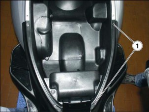
LUGGAGE RACK REMOVAL
TORQUE WRENCH SETTINGS
Screws (1) 10 Nm (1.0 kgm)
Screws (2) 24 Nm (2.4 kgm)

-
Raise the saddle, 7.1.2.
-
Remove the luggage rack cover.

-
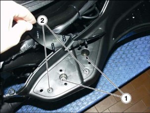
Release and remove the two screws (1) and collect the two
washers.
-
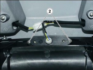
Release and remove the two screws (2). 

-
Remove the luggage rack.

-
TAIL REMOVAL

-
Remove the luggage rack, 7.1.4.
-
Remove both rear side panels, 7.1.3.
-
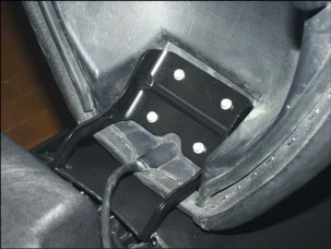
Release and remove the three upper screws (1) on both sides.
-
Release and remove the lower screw (2) on both sides. 
-
Shift the tail and disconnect the tail light connector. 

-
Disconnect the saddle releasing cable.
-
Remove the complete tail.

-
REMOVING THE NUMBER PLATE HOLDER
-
Release and remove the four screws (1) on both sides.
-
Shift the number plate holder.
-
Release and remove the two screws of the bulb holder (2).
-
Remove the number plate holder.

-
REMOVING THE CENTRAL TUNNEL

-
Remove the saddle, 7.1.2.
-
Remove the tail, 7.1.5.
-
Remove the legshield, 7.1.9.
 WARNING WARNING
Proceed carefully. Do not damage the tab
and/or its recesses.
-
Lift and remove the mat on both sides with your hands.
-
Release and remove the five screws (1) on both sides.
-
Release and remove the six screws (2) on both sides. 
-
Insert the ignition key into the tank lock.
-
Press and turn the key anticlockwise.
-
Lift the filler cap flap.

-
Remove the rubber gaiter placed underneath the fuel filler cap.
NOTE Place
a clean cloth into the filler cap opening.

 WARNING WARNING
Proceed carefully. Do not damage the tab
and/or its recesses.
-
Remove the central tunnel pulling in a rearward motion.

-
AIR DAM REMOVAL
-
Place the vehicle on the centre stand.
-
Lift and remove the front mat with your hands on both sides.

-
Lift and remove the rear mat with your hands on both sides.
-
Release and remove the six screws (1) on both sides.


-
Release and remove the screw (2) at the rear end on both sides.
-
Release and remove the three screws (3) at the front end.
-
Lower the side stand.
-
Remove the air dam.
-
LEGSHIELD REMOVAL
-
Place the vehicle on the centre stand.
-
Release and remove the eight screws (1) at the sides.

-
Insert the ignition key into the fuel tank lock.
-
Press and turn the key anticlockwise.
-
Lift the filler cap flap.
-
Release and remove the two screws (2).

-
Lift the front cover.
-
Release and remove the two screws (3) on both sides.
 WARNING WARNING
Proceed carefully. Do not damage the tab
and/or its recesses.
-
Remove the legshield.

-
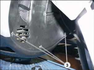
FRONT COVER REMOVAL
-
Release and remove the screw (1) at the rear end on both sides.

-
Release and remove the two screws (2) at the front end.
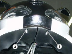
-
Release and remove the two screws (3) at the lower end.
-
Remove the front cover.
-
SCREEN REMOVAL

-
Remove the front cover, 7.1.10.
-
Remove both mirrors, 7.1.12.
-
Release and remove the two front screws (1).
-
Remove the windshield screen.
-
REAR-VIEW MIRROR REMOVAL
TORQUE WRENCH SETTINGS
Screws (2) 10 Nm (1.0 kgm)
NOTE The
procedures described below apply to both mirrors.
-
Slip off the rubber gaiter.
-
Release and remove the two screws (1).
-
Remove the outer cover. 

-
Release and remove the two screws (2).
-
Remove the mirror.
-
REMOVING THE SIDE FAIRINGS
NOTE The
procedures described below apply to both fairings.

-
Remove the front cover, 7.1.10.
-
Remove the legshield, 7.1.9.
-
Release and remove the upper screw (1) on both sides.
-
Release and remove the screw (2) on both sides. 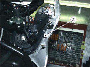

-
Release and remove the four screws (3) on the inside.
-
Remove the side fairing.
-
FRONT MUDGUARD REMOVAL
TORQUE WRENCH SETTINGS
Screws (1) 7 Nm (0.7 kgm)
-
Place the vehicle on the centre stand.
-
Release and remove the two screws (1) at both sides.
-
Remove the front mudguard.
-
REAR MUDGUARD REMOVAL
TORQUE WRENCH SETTINGS
Airbox screws (1) 8 Nm (0.8 kgm)
Screws (2) 12 Nm (1.2 kgm)
-
Unscrew the two retaining screws (1) of the airbox.

-
Unscrew the three retaining screws (2) and collect the cable
retainer.
-
Remove the rear mudguard.
-
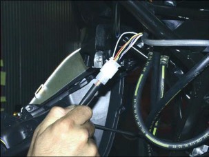
HELMET COMPARTMENT REMOVAL

-
Remove the tail, 7.1.5.
-
Remove the saddle, 7.1.2.

-
Remove the battery and extract the main fuse carrier,
7.2.1.
-
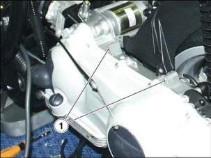
Release and remove the two screws (1) at the front end.

-
Release and remove the two screws (2) at the rear end.
-
Lift the helmet compartment.
-
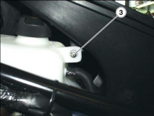
Release and remove the two retaining screws (3) of the expansion
reservoir.
-
Shift the expansion reservoir, but leave it connected to the
coolant hoses.
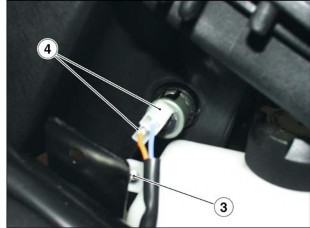
-
Disconnect the two power socket connectors (4).
-
Remove the helmet compartment.
-
HANDLEBAR COVER REMOVAL
-
Release and remove the two screws (1).
-
Remove the upper cover.

-
Release and remove the screw (2) at the front end on both sides.
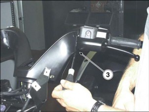
-
Release and remove the screw (3) at the lower end on both sides.

-
Release and remove the three screws (4).

-
Remove the upper handlebar cover.
-
Release and remove the two screws (5).
-
Remove the lower handlebar cover.
-
SPLASHGUARD REMOVAL

-
Remove the complete headstock, 7.8.1.
-
Remove the central tunnel, 7.1.7.
-
Shear the tie (1) on both sides.
-
Withdraw both air scoops from the radiator.
-
Release and remove the four screws (2) at both sides. 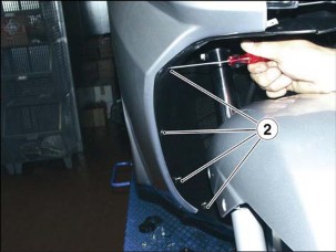

-
Release and remove the centre screw (3).
-
Remove the splashguard.

-
BATTERY REMOVAL

-
Perform the first four operations described at paragraph 2.4.2.
-
Disconnect the negative (-) cable first and then the
positive (+) cable.
-
Disconnect the breather hose from the battery.
-
Remove the battery.
-
ENGINE CONTROL UNIT REMOVAL

-
VOLTAGE REGULATOR REMOVAL

-
Remove the tail, 7.1.5.
-
Disconnect the voltage regulator connector (1).
-
Release and remove the two screws (2).
-
Remove the voltage regulator.

-
REMOVING THE RIGHT SWITCH
-
Release and remove the three screws (1) at the lower end.
-
Release and remove the screw (2).
-
Remove the switch lower cover.
-
Disconnect the engine kill switch connector. 

-
Disconnect the starter connector.
-
Remove the switch upper cover.

-
REMOVING THE LEFT SWITCH
-
Release and remove the three screws (1) at the lower end.
-
Release and remove the screw (2).
-
Remove the switch lower cover.
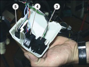
-
Disconnect the light connector (3).
-
Disconnect the direction indicator connector (4).
-
Disconnect the horn connector (5).
-
Remove the switch upper cover.
-
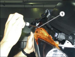
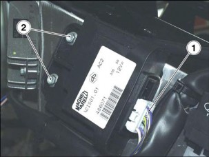
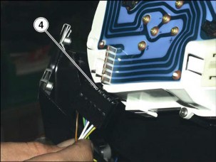
DASHBOARD REMOVAL

-
Remove the windshield, 7.1.11.
-
Release and remove the dashboard retaining screw (1) on both
sides.
-
Lift the dashboard. 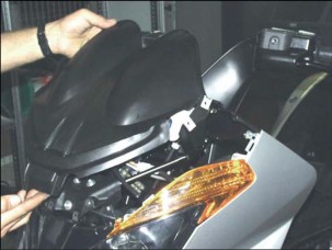
-
Disconnect the speedometer cable. 

-
Disconnect the three dashboard connectors (2-3-4). Proceed
gently or the flexible printed circuit might damage.
-
Remove the dashboard.
-
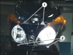
HEADLIGHT REMOVAL

-
Remove both side fairings, 7.1.13.
-
Release and remove the two upper screws (1).
-
Release and remove the two lower screws (2).

-
Disconnect the two direction indicator connectors on both sides.
-
Disconnect the headlight connector.
-
Remove the headlight.

содержание ..
1
2
3
4
5
6
7
8
..
|
|
|

