содержание .. 1 2 3 4 5 6 7 ..
Aprilia scooter (manual) - part 5
-
-
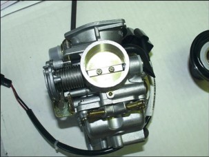
ASSEMBLING THE CARBURETOR
-
Before reassembling the carburetor, thoroughly clean carburetor body with fuel and compressed air.
-
Take special care to the fuel delivery line and to the metering rod location.
-
Accurately check full-power circuit air calibration.
-
As for the idling circuit, make sure that the following parts are perfectly clean: air calibration, outfeed section managed by the flow adjuster screw, progression holes at the throttle.
NOTE The idling air of the 200 cc version is controlled by two calibrations. The cut-off calibration is directly derived from the carburetor body.

-
Check that the five closing balls of the working ducts are positioned on the carburetor body.
-
Check that the surface mating float chamber and membrane are not dent.
-
Check that the vacuum valve duct is not scored.
-
Check that the throttle valve and shaft are not excessively worn.
-
Check that the metering rod location is not excessively worn.
-
If this is the case, change the carburetor.
NOTE To avoid any damage, do not insert metal parts into the gauged sections.

-
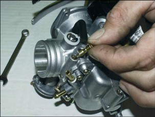
Thoroughly wash and blow idling jet (1). Refit.
-
Thoroughly wash and blow spray nozzle full-power circuit, diffuser and jet.
-
Install the spray nozzle into the carburetor body. Make sure that the cylindrical side, which is shorter, is facing the diffuser.
-
Fit the diffuser. Make sure that the spray nozzle is properly positioned. Lock in place.
-
Fit the full-power jet.

-
Check that the surface of the tapered metering rod mating the dampened pin and the return spring is not worn.
-
In case of wear, change the metering rod.
-
Check that the float surface at the pin location or at the metering rod contact plate is not worn. Check also for fuel leaks.
-
In case of malfunctioning, change the parts.
-
To fit the float with metering rod, insert the pin from the fuel feeding side.
NOTE Take care that the return spring is correctly installed into the float plate.
CHECKING THE LEVEL
-
With the carburetor in upside-down position, make sure that the float mating surface is parallel to the float chamber surface.
-
If this is not the case, change the metering rod metal plate direction until reaching the above position.
-
If the plate shape is changed, make sure that it is still parallel to the float pin.
NOTE With the carburetor in upside-down position, the float weight should not counteract the tapered metering rod spring thrust. If this is not the case, check that the float is free from fuel. Change the float and the tapered metering rod, if necessary.

-
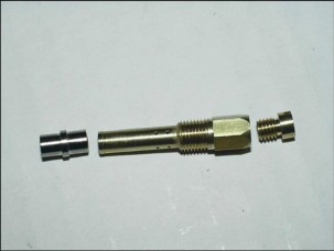
Thoroughly wash and blow the fuel conveyor cap (2) and fit it onto the starter.
NOTE Failure to fit this part leads to a worse cold starting, since the starter jet takes old fuel from the float chamber bottom.

-
Remove the float chamber exhaust screw (3), thoroughly wash and blow the float chamber. Make sure to perfectly clean the pick-up pump intake and delivery valve.
-
As these are one-way valves, gently blow with compressed air into the intake valve working from the float chamber inner side and into the exhaust valve working from the pump piston seat.

-
Check the pick-up pump piston and its seat into the float chamber for wear.
-
If this is the case, change the worn parts.
-
Check the pick-up pump piston return spring for wear.
-
Fit a new OR-seal and a new bellows seal. Refit the piston unit onto the float chamber.
-
Fit a new OR-seal in the float chamber exhaust screw. Tighten the screw.

-
To check screw proper sealing, pour a small quantity of fuel into the float chamber.
-
Fit a new seal on the float chamber.
-
Fit the float chamber to the carburetor body. Tighten the four screws.
-
Thoroughly wash and blow the flow adjuster screw. Fit a new OR-seal.
-
Pre-assemble the following parts on the screw in the following order: spring, washer and OR-seal.
-
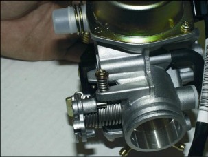
Screw the flow screw on the carburetor body.
-
Screw final position will have to be defined according to the exhaust gases analysis.
-
Prepare carburetor for adjustment by loosening the screw by three turns starting from the closed position.
-
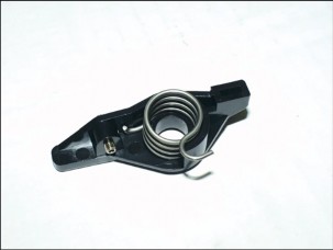
Check that the pick-up pump control rocker arm is not excessively worn.
-
Check that the rocker arm set screw juts of:
-
125 cc engine: 3.7 mm
-
200 cc engine: 3.2 mm.
-
-
Check the rocker arm return spring for yielding.
-
Pre-assemble spring and rocker arm.
-
Keep the throttle open and fit the rocker arm on the carburetor.
-
Tighten rocker arm screw.
-
Make sure that the mechanism works properly.

CHECKING THE VACUUM VALVE AND THE TAPERED METERING ROD
-
Undo the bayonet-coupling by 1/8th of a turn and remove it. Remove spring and vacuum valve metering rod.
-
Check the metering rod for wear and that the retainer is positioned inside the third notch.
-
Check the outer diameter vacuum valve for scoring.
-
Check that the two vacuum feeding holes are not obstructed.
NOTE The 2 holes have different diameters.

-
Make sure that the membrane is not broken or hardened. If this is the case, change it.
-
Refit the tapered metering rod on the vacuum valve.
-
Make sure that the spring is correctly positioned on the metering rod and that coupling is perfectly seated.
-
To fit the coupling, turn it by 1/8th of a turn.
-
Refit the vacuum valve on the carburetor. Make sure that the tapered metering rod seats into the spray nozzle.
-
To time vacuum valve rotation, insert membrane end into its location. The membrane is correctly fitted to the valve when vacuum main feeding hole is in axialposition with the choke tube, on the throttle side (see figure).
-
Refit spring onto valve.
-
To refit vacuum chamber cover, make sure that the reference on cover matches with that on the membrane.
-
Tighten screws to the specified torque.
-
Check for cut-off valve proper positioning, for 200 cc version only. Check that the membrane is not broken or hardened. Check spring free length.
Standard length: 24 mm
-
Refit membrane with the metal pin on valve. Refit spring and cover. Make sure that cover vacuum port is facing upwards.
-
Wash and blow starter mount.
-
Refit a new seal on carburetor body and tighten the two fastening screws.
-
-
CHECKING THE AUTOMATIC STARTER
-
Check that the automatic starter piston is not scored or oxidized.
-
Check that the piston can run smoothly into its mount.
-
Check that the piston seal is not out of shape.
-
The starter must be switched on and off depending on the room temperature.
-
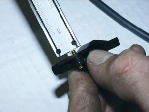
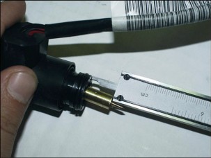
Measure the piston jut, as shown in the figure, and check the corresponding value.
-
Make sure that the starter is set to room temperature. Jut value: 12.5 -: 13 mm at about 20°C
-
The starter will have to switch progressively off by means of the electric heating.
-
Check starter resistance with the starter set to room temperature.
Resistance: about 30 ohm
-
Using a 12 V battery, feed the automatic starter and check that the piston reaches max. jut.
Max. jut: 18.5 -: 19 mm Max. time: 5 min
-
Heating real time depends on room temperature.
-
In case of juts, resistances or times different from the recommended ones, change the starter.

-
Fit starter to carburetor. Take care to correctly position the OR-seal, install the knurled plate on the starter, and tighten the two screws (1).
-
Aim the starter as shown in the figure.
-
Fit the protective cover.
-
-
ADJUSTING THE IDLING MIXTURE
-
-
The idling mixture does not need to be often adjusted. This adjustment shall be made in full compliance with some dispositions.
-
Before proceeding to carburetor adjustment, make sure that the following conditions are respected: good lubrication, valve clearance and timing, spark plug in perfect conditions, sealed and clean air filter, sealed exhaust system.
-
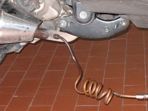
Connect the exhaust gas tester to the vehicle, i.e. insert the tester copper probe into threaded pick-up point before the silencer.

-
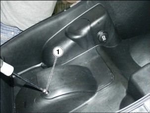
Close the secondary air inlet (1) on exhaust manifold.
-
Warm engine up, running it for at least five minutes at about 2000 rpm.
NOTE It is very important that the probe be fitted before the catalytic converter so not to take up exhaust gases already oxidised by the catalytic converter.
NOTE The exhaust gas tester must be heated in advance and should ensure gas reading and correct gas capacity reset. Should these recommendations not be respected, the reading will not be correct.
-
Using a duly-prepared oil filler cap, connect multimeter thermometer to sump.
-
Start engine and wait for oil temperature to be between
70 -: 80 °C (158 -: 176 °F) to start idling mixture adjustment.
-
Using the tester rev counter or a separate rev counter, adjust the idling screw until reaching a rpm value of 1700 -: 1800 g/min.
NOTE The ignition system produces a big power. In case unsuitable rev counters are used, some reading errors may arise. The rev counter is suitable for this operation whenever it can take readings also at high rpm values, such as 6000 + 8000 rpm.

-
Adjust the flow screw until reaching a CO rate of 2,5 -: 3,1%. To increase the CO rate (rich mixture) loosen the screw, while to decrease the CO rate (lean mixture) turn the screw in the opposite direction.
-
If the rpm value increases after the flow screw adjustment, adjust the rpm value again and, if necessary, adjust also the flow screw until reaching the recommended values.
-
The idling mixture is correct when the oil temperature, rpm and CO values are respected.
-
The tester gives further information, such as:
-
Carbon dioxide (CO2) percentage. This value is opposite to the CO rate, namely with correct values above 12.5%. Non-conforming values indicate that the exhaust system is not perfectly sealed.
-
-
Unburnt hydrocarbons (HC) measured per million (PPM). The HC value decreases as the rpm increases. With the engine at idling speed, the standard value is of 200 -: 400 PPM. These values apply to an engine with motorcycle timing diagram. Values far above these limits can be caused by engine misfiring due to too a rich mixture (low CO rate), ignition defects,improper timing or jamming or unsealed exhaust valves.
Should some difficulties in the CO rate adjustment arise, carefully check:
-
Carburetor cleaning
-
Automatic starter operation
-
Seat-tapered metering rod operation
-
Float chamber level adjustment.
COOLING SYSTEM 5
SUMMARY
-
COOLING SYSTEM DIAGRAM 3
-
COOLING SYSTEM DIAGRAM 3
-
-
COOLANT 4
-
CHANGING COOLANT 4
-
-
RADIATOR 5
-
REMOVING THE RADIATOR 5
-
REMOVING THE ELECTRIC FAN 7
-
-
WATER TEMPERATURE SENSOR 9
-
REMOVING THE WATER TEMPERATURE SENSOR 9
-
-
REMOVING THE EXPANSION RESERVOIR 10
-
REMOVING THE EXPANSION RESERVOIR. 10
-
-
COOLING SYSTEM DIAGRAM
-
COOLING SYSTEM DIAGRAM
The centrifugal pump, which is located inside and driven by engine, sucks coolant from radiator and sends it to the cylinder and head ducts to cool engine inner parts.


The fluid volume increase, which is caused by the temperature increase, is compensated inside the expansion reservoir. Check the “LOW” and “FULL” references to check and top up the fluid level, see 2.9.1.
For coolant, see 1.3.1.
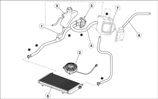
Key:
-
Expansion reservoir connection tube
-
Electric fan
-
Centrifugal pump
-
Cylinder – pump tube
-
Expansion reservoir
-
Radiator
-
Cylinder head cover
-
Engine breather pipe

-
-
-
COOLANT
-
CHANGING COOLANT
-
DRAINING THE CIRCUIT
![]()
-
Remove the expansion reservoir cap, 5.5.1.
-
Loosen clamp (2) and slide out hose (1).
-
Let the fluid flow into a suitable container for collection. FILLING THE CRICUIT

-
Position hose (1) and secure it in place with clamp (2).
-
Top up coolant, 2.9.1.

-
Start engine and let it run until the cooling fan switches on. Allow engine to cool down and check again coolant level into expansion reservoir.
-
Top up, if necessary. 2.9.1.

-
RADIATOR
-
REMOVING THE RADIATOR


-
-
-
Drain the circuit, 2.12.2.
-
Remove lower protection, 7.1.8.
-
Disconnect electric fan connector.
-
Disconnect the two connectors on temperature switch.


-
Working from both sides, cut clamp (1).
-
Slide both air intake manifolds out of radiator.
-
Working from both sides, loosen and remove the two screws (2).

-
Undo and remove central screw (3).
-
Remove clamps.

-
Slide hoses (4) out of radiator.
-
Remove radiator.
-
REMOVING THE ELECTRIC FAN

-
-
Lower the radiator, but leave it connected to hoses,
5.3.1.
 WARNING
Proceed with extreme care not to damage radiator
fins.

-
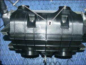
Undo and remove the two nuts (1) on the front side. Keep the screws.
-
Undo and remove the two nuts (2) on the rear side. Keep the screws.
-
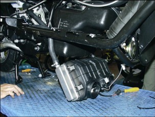
Remove the conveyor box.

-
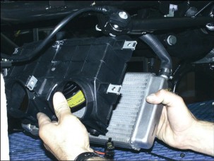
Undo and remove the two screws (3).
-
Remove the electric fan.
содержание .. 1 2 3 4 5 6 7 ..