Volkswagen Golf / Golf GTI / Jetta. Manual - part 430


  Index      Volkswagen     Volkswagen Golf / Golf GTI / Jetta - service repair manual 1999-2005 year


Search            copyright infringement  


Content   ..  428  429  430  431   ..


Volkswagen Golf / Golf GTI / Jetta. Manual - part 430


45-98


Make sure the wiring is not twisted 
when installing the speed sensor 
wiring in the wheel housing.  

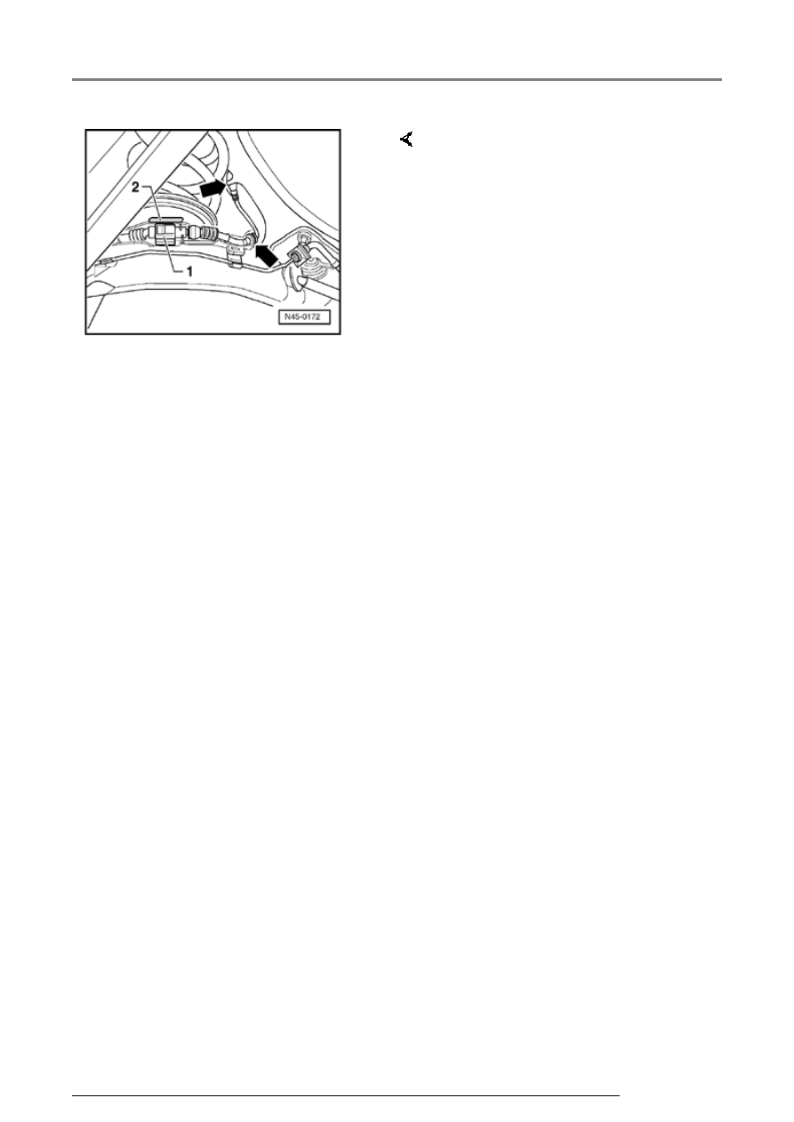
-  Connect speed sensor to speed 

sensor wiring -1- and close 
connector cover -2-. 

-  Clip in speed sensor wiring 

(arrows). 

-  Cut 2-pin connector off new 

speed sensor wiring with wire 
stripper pliers. 

-  Strip 15 mm (5/8 in.) of insulation 

from end of wire with wire 
strippers and bend back half. 

-  Connect speed sensor wiring with 

help of suitable crimp connector 
from wiring harness repair set 
VAS 1978. 

ABS system components for front and rear axles, removing and installing

45-99


ESP system components, 
removing and installing 


   A description of construction and function of 

ESP system is found in Self Study Program 
861103 Volkswagen Handling Controls.  


   When the individual sensors or senders are 

changed, a zero compensation must be 
carried out for the changed component.  

ESP system components, removing and installing

45-100


Sender for rotation rate -G202- and 
sensor for transverse acceleration -
G200-, removing and installing 


Note:  


The removal and installation sequence for the 
sender for rotation rate -G202- and the sensor for 
transverse acceleration -G200- is identical 
except for the mounting bracket for each 
component.


Removing  


-  Request radio code on vehicles with coded radio 

if necessary. 


-  Disconnect battery. 


-  Remove Qty. 2 screws -1-. 

-  Unclip top of trim -2- 

-  Remove Qty. 2 screws -3- 

-  Unclip top of trim -4-. 

ESP system components, removing and installing

45-101


-  Remove Qty. 7 screws (arrows). 

-  Take off reinforcement -1-. 


-  The sender for rotation rate -

G202- -1- and the sensor for 
transverse acceleration -G200- -
2- are located on the steering 
column -3- bearing bracket. 

a - Steering column 

ESP system components, removing and installing


Content   ..  428  429  430  431   ..