Volkswagen Golf / Golf GTI / Jetta. Manual - part 410


  Index      Volkswagen     Volkswagen Golf / Golf GTI / Jetta - service repair manual 1999-2005 year


Search            copyright infringement  


Content   ..  408  409  410  411   ..


Volkswagen Golf / Golf GTI / Jetta. Manual - part 410


45-30


ABS wheel speed sensor wiring to 
rear axle, removing and installing 


Required special tools  


Removing  


Repair Manual, Body Interior, 

Repair Group 70


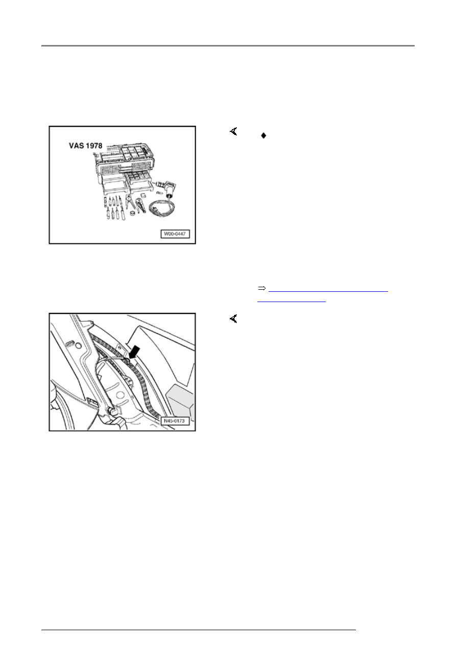
 VAS 1978 Wirng harness repair 

set 

-  Obtain radio code on vehicles 

with coded radio. 

-  Disconnect battery 

-  Disconnect wheel speed sensor 

wiring connector. 

-  Remove rear interior side panel 

trim. 


-  Strip insulation (arrow) from 

shrink connection. 

-  Cut speed sensor wiring in front 

of spliced connection with 
stripping pliers from VAS 1978 
wiring repair kit and remove faulty 
wiring. 

ABS system components for front axle, removing and installing

45-31


-  Strip insulation at wiring end by 

15 mm (5/8 in.) using stripping 
pliers from repair kit and fold over 
stripped wire portion. 

-  Install new speed sensor wiring. 

-  Connect wheel speed sensor to 

speed sensor wiring. 


Note:  

Do not twist wires in the wheel well. 

-  Secure wheel speed sensor wire 

(arrows). 

-  Cut 2-pin connector at new speed 

sensor wire (if installed) using 
stripping pliers from repair kit. 

-  Strip 15 mm (5/8 in.) insulation off 

wire end and fold over stripped 
wire. 

-  Connect wheel speed sensor wire 

using correct connector from 
wiring repair kit VAS 1978. 

ABS system components for front axle, removing and installing

45-32


Anti-lock brake system (ABS) 
Mark 60 


   Only the following versions of the ABS Mark 

60 are installed in this vehicle:   


 ABS 


 ABS/EDL with electronic differential lock 


 ABS/EDL/ASR with electronic differential lock 

and traction control system 


 ABS/EDL/ASR/ESP with electronic stabilization 

program 

Anti-lock brake system (ABS) Mark 60

45-33


General information on this 
ABS, ABS/EDL 


     Application of ABS in a left-hand 

drive vehicle.  

For vehicles from my 02.02 the 
mechanical brake assist is installed. 
It's integrated in the brake booster 
for the use within the system as 
special equipment. This can be 
recognized by the replacement part 
number.  

Repairing the mechanical brake 
assist is not possible. The brake 
booster must be replaced complete.  

Function test of brake assist in brake 
booster 


Page 47-57


The ABS brake system is divided 
diagonally. The brake booster is a 
pneumatic type and the vacuum is 
provided by brake booster.  

Vehicles with Mark 60 ABS do not 
have a mechanical brake pressure 
regulator. A specially matched 
software in the control module 
controls the rear axle brake pressure 
regulation.  

1 - Brake booster 

2 - Hydraulic unit 

3 - Control module, 47-pin (screwed 
to hydraulic unit). Two 4.8 mm wide 
contacts are located at both ends of 
the connection. 

Anti-lock brake system (ABS) Mark 60


Content   ..  408  409  410  411   ..