Volkswagen Golf / Golf GTI / Jetta. Manual - part 238
24-206
Brake Light Switch -F- and
Brake Pedal Switch (cruise
control/Diesel Direct Fuel
Injection) -F47- signal,
checking
Special tools, materials and
equipment
Note:
All functions which could previously
be performed with VAG 1551/1552
can also be performed with the VAS
5051.
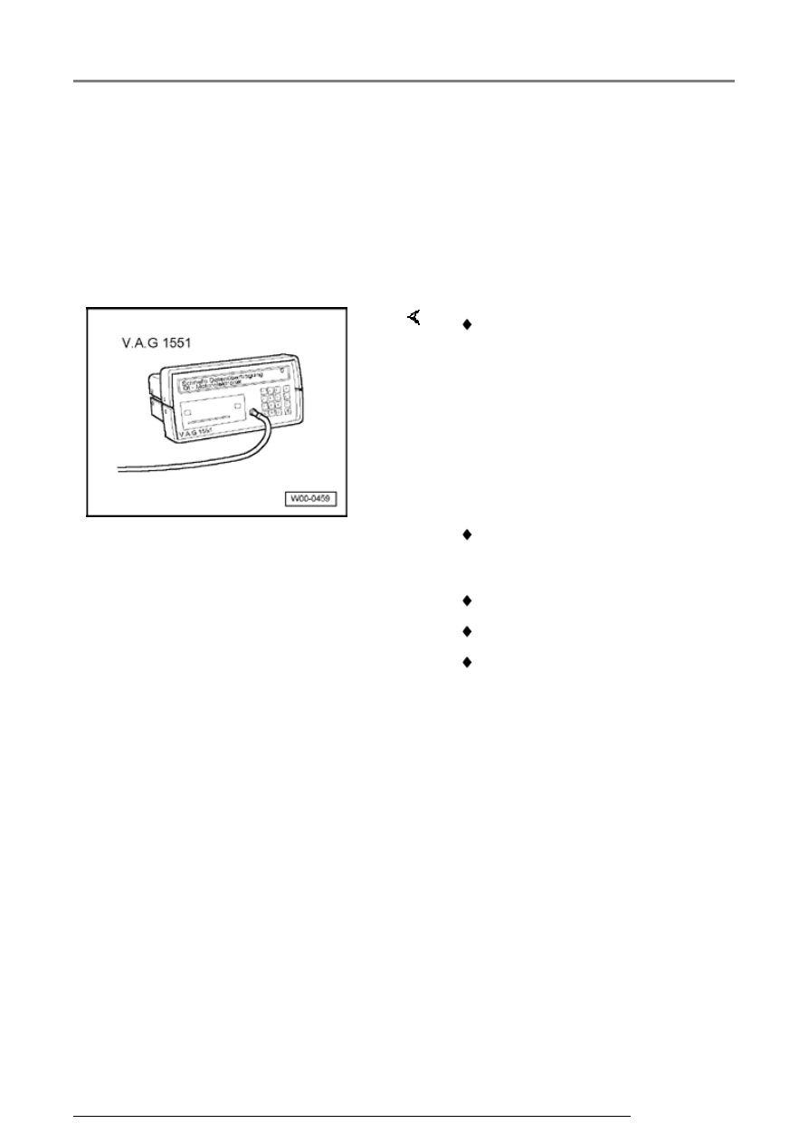
VAG 1551 Scan tool (or VAG
1552) with VAG 1551/3 adapter
cable
VAG 1526 or Fluke 83 Hand
multimeter or VAG 1715
multimeter
VAG 1594 Adapter set
VAG 1598/31 test box
Electrical Wiring Diagrams
Additional signals, checking