Volkswagen Golf / Golf GTI / Jetta. Manual - part 168


  Index      Volkswagen     Volkswagen Golf / Golf GTI / Jetta - service repair manual 1999-2005 year


Search            copyright infringement  


Content   ..  166  167  168  169   ..


Volkswagen Golf / Golf GTI / Jetta. Manual - part 168


01-214


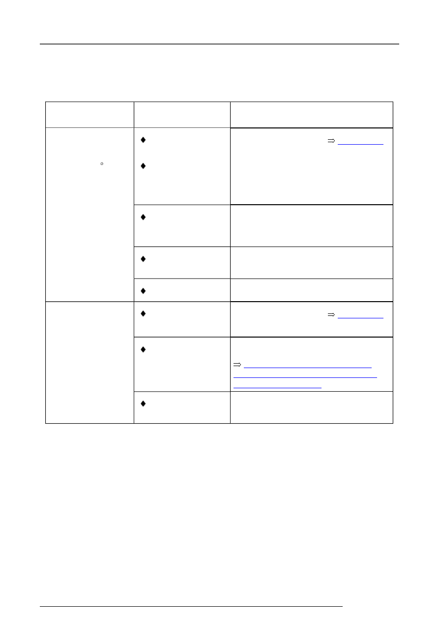
Evaluating display groups 22 to 24, display zones 3 and 4 - Ignition timing 
retardation cyl. 1 to 6 
 

Appears on 

display  

Possible cause  

Corrective action  

All cylinders 

between  

8.0...15.0  CA  

and at the same 

display values  

 Knock sensor 

faulty 

 Connector 

corroded 

- Check knock sensors 


Page 28-30


 Knock sensor 

incorrectly 
tightened 

- Loosen knock sensor and tighten to 
20 Nm 


 Accessories on 

engine loose 

- Tighten accessories 


 Poor fuel quality 

- Change type of fuel 

One cylinder 

deviates greatly from 

the others  

 Connector 

corroded 

- Check knock sensors 


Page 28-30


 Engine damaged 


Repair Manual, 2.8 Liter VR6 4V 

Engine Mechanical, Engine Code(s): 
BDF; Repair Group 15


- Check compression pressures: 


 Accessories on 

engine loose 

- Tighten accessories 

Measured value (data) blocks

01-215


Display group 28 - Ignition - Knock control  

 Control module in function "04-Basic setting" 

 Vehicle stationary, engine running at increased idle speed (only with brake and 

accelerator pedals depressed) 

System in basic 
setting 28  


 Indicated on display     


xxxx 
rpm  

xxx.x 

%  

xxx.x 

C  

Text     


 Display zones  

Specification  

Evaluation  


Result of knock control 
diagnosis  

(Test ON / Test OFF / 
Sys. OK. / Sys. n.OK.)  


Syst. OK.  


---  


Engine coolant temperature  

85.0...110.0 

C  


Page 01-

195


Engine load  

12.0...100.0 %  

---  


Engine speed  

Approx. 2300 

rpm  

---  

Measured value (data) blocks

01-216


Measured value blocks, display groups 30...33, 99 - Oxygen Sensor (O2S) 
control, evaluating


Display group 30 - Oxygen Sensor (O2S) control  

 Engine running at idle 

Read measured value 
block 30  


 Indicated on display     


xxx  

xxx  

---  

---  


 Display zones  

Specification   Evaluation  


No display  

---  

---  


No display  

---  

---  


Oxygen Sensor (O2S) control status after 
Three Way Catalytic Converter (TWC)  

 Three Way Catalytic Converter 

(TWC) temperature at least 380.0 

C (

display group 34, display zone 

2) 

111  


Page 01-

217


Oxygen Sensor (O2S) control status before 
Three Way Catalytic Converter (TWC)  

 Three Way Catalytic Converter (TWC) 

temperature at least 380.0  C (

display 

group 34, display zone 2) 

111  


Page 01-

217


Note on display zone 2:  

The 3rd character in the digit number block will not be set to 1 until in part load range.  

Measured value (data) blocks

01-217


Significance of characters in 3 digit number block, display zones 1 and 2 - Status 
of Oxygen Sensor (O2S) control before and after Three Way Catalytic Converter 
(TWC) 
 

Significance if display = 1  

1   2   3  

Significance  


   1   Oxygen Sensor (O2S) control active  

   1     

Oxygen Sensor (O2S) operationally ready  

1        

Oxygen Sensor (O2S) heating on  

Note:  

 Depending on the status of the Oxygen Sensor (O2S) control, 0 or 1 may appear 

alternately in the 3 digit block, but the Oxygen Sensor (O2S) must always be 
operationally ready.
 

 The 1 set for the Oxygen Sensor (O2S) heating may sporadically be 0 because the 

heating is pulsed. 

Measured value (data) blocks


Content   ..  166  167  168  169   ..