Volkswagen Fox (2004 year). Manual - part 14


  Index      Volkswagen     Volkswagen Fox - service repair manual 2004 year


Search            copyright infringement  


Content   ..  12  13  14  15   ..


Volkswagen Fox (2004 year). Manual - part 14


Note

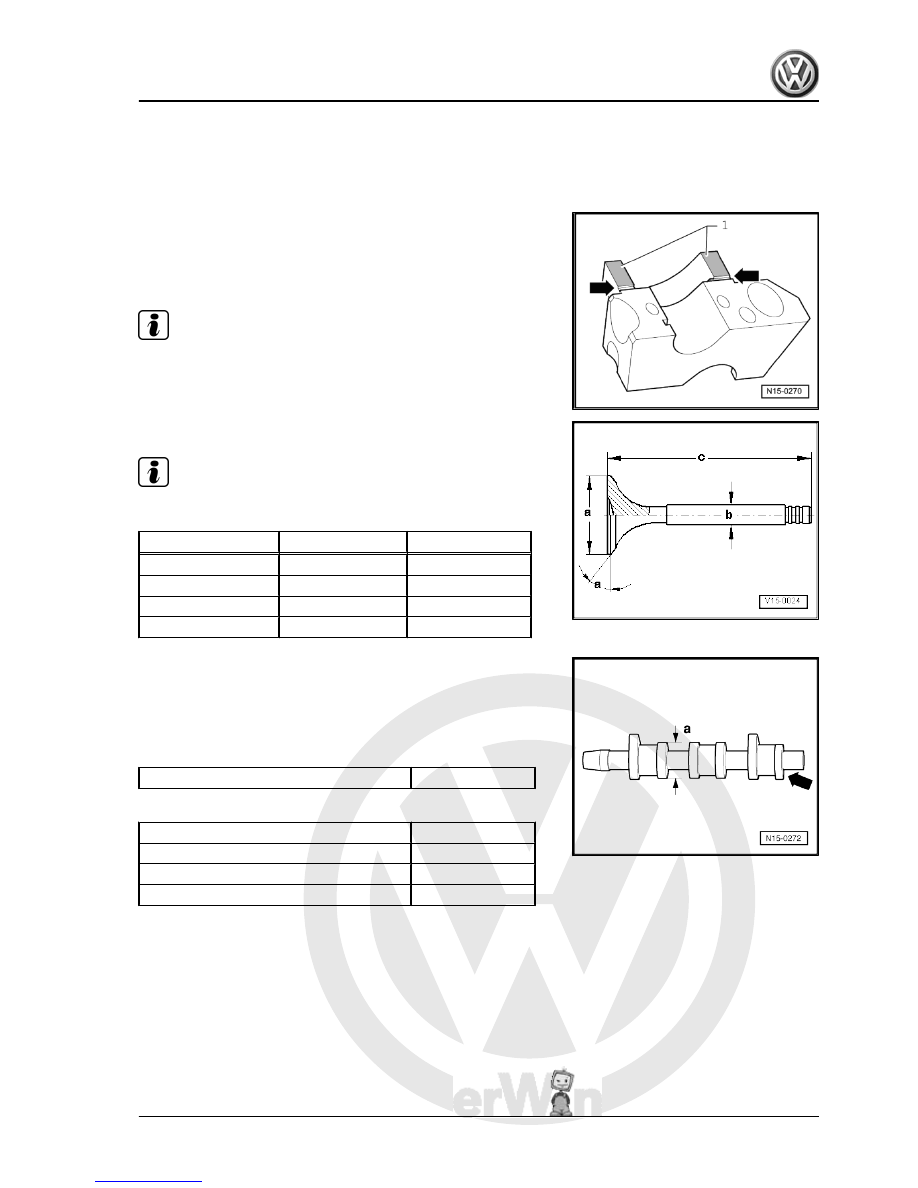
Ensure that no sealant enters grooves -arrows-.

Bearing cap 4 is identified as bearing cap 5.

Valve dimensions

Note

Valves cannot be reworked. Only lapping-in is permitted.

Dimension

Intake valve

Escape valve

∅ a

mm

35,95

31,45

∅ b

mm

6,980

6,956

c

mm

89,95

89,95

α

∠°

45

45

Valve identification and synchronization
Identification
♦ Cam base diameter: -a- = ∅ 52.8 mm.
♦ Identification via numbers and letters on the external cam sur‐

face of the escape valve at cylinder 3:

Cylinder 3 -arrow-

1 R

Valve synchronization in the opening of 1-mm valve

Intake opens after TDC

15,8°

Intake closes after BDC

25,3°

Exhaust opens before BDC

28,2°

Exhaust closes before TDC

18,7°

2.1

Valve seats - rework

Special tools and workshop equipment required
♦ Depth gauge
♦ Valve seat recovery tool

Fox 2004 ➤

2. Valve command - repair    

53


In case of repairs to engines with leaking valves, simply re‐

working or replacing the seats and valves is insufficient. Es‐

pecially in engines with high milage, the valve guides must

also be checked for wear.

The valve seats should only be sufficiently reworked to pro‐

duce a perfect seating pattern. The maximum reworking di‐

mension must be calculated before undertaking the tasks.

When the rework measurement is exceeded, the hydraulic

compensation function of the tappets will not be guaranteed,

and the engine head must be replaced.

2.1.1

Calculating the maximum reworking di‐

mension allowed

– Install valve and firmly press it against seat.

Note

In case the valve is replaced during repairs, use new valve for

measurement.

– Measure the distance -a- between valve stem end and engine

head upper edge.

– Calculate max. permissible reworking dimension from meas‐

ured distance -a-and minimum dimension.

Minimum dimensions: Intake valve 43.4 mm Escape valve 43.2

mm.
Distance measured minus minimum distance = maximum per‐

mitted reworking dimension.
Example:

-

Measured distance

Minimum dimension

44,1

43,4

mm

mm

=

Max. reworking dimension perm.

0,7 mm

2.1.2

Reworking intake valve seat

a

=∅35.7 mm

b

= 1.6 mm

45°

= Valve seat angle

Note

. The 30° angle in the valve seat base is crucial for ensuring the

correct gas flow.

Fox 2004 ➤

54


a

=∅31.4 mm

b

= 2.7 mm

45°

= Valve seat angle

2.2

Valve guides - check

Special tools and workshop equipment required
♦ Support -VW 387-
♦ Dial gauge
Test sequence
– Place a new valve on the guide. Valve stem end shall be

aligned with guide. Due to differences in valve stem diameters,

fit intake valves in the intake guides and exhaust valves in ex‐

haust guides.

– Determine tilting clearance. Wear limit: max. 1.3 mm.
– Cylinder head shall be replaced if the clearance is greater than

wear limit.

Fox 2004 ➤

2. Valve command - repair    

55


Special tools and workshop

equipment required
♦ Device -2036-
♦ Extractor -3047A-
♦ Fitter -3129-
♦ Lever -VW 541/1A-
♦ Supporting part -VW 541/5-

2.3.1

Removal

(with engine head installed).
– Remove camshaft 

⇒ page 58

 .

– Remove tappets and place them with contact surface turned

downwards. When doing this, ensure that the tappets are not

interchanged.

– Adjust piston of respective cylinder to top dead centre (TDC).

Fox 2004 ➤

56


Content   ..  12  13  14  15   ..