Suzuki Grand Vitara JB419. Manual - part 126


  Index      Suzuki     Suzuki Grand Vitara JB419 (with F9Q engine) - service repair manual 2007 year


Search            


Content   ..  124  125  126  127   ..


Suzuki Grand Vitara JB419. Manual - part 126


Air Conditioning System:  7B-10

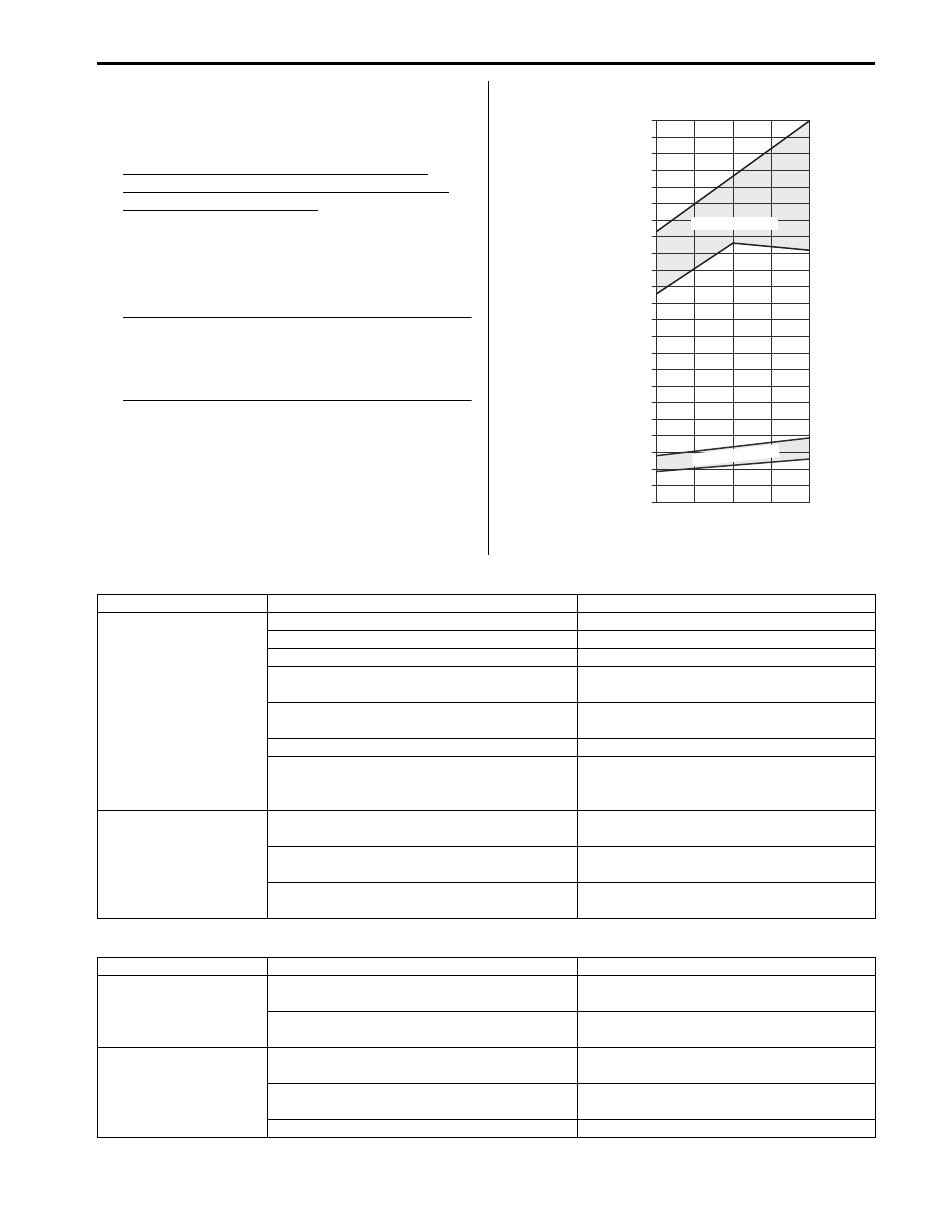
10) Check for each pressure of low side and high side if 

it is within shaded range of graph. If each gauge 
reading is out of specified pressure, correct defective 
part referring to the table.

Low side and high side pressure example, 
gauges should read as follows when ambient 
temperature is 30 

°C (86 °F)

Pressure on high pressure gauge (HI): 1570 – 
1970 kPa (15.7 – 19.7 kg/cm

2

, 223 – 280 psi)

Pressure on high pressure gauge (LO): 230 – 330 
kPa (2.3 – 3.3 kg/cm

2

, 33 – 47 psi)

NOTE
Pressure registered on gauge varies with 
ambient temperature. Therefore, use the 
graphs when determining if pressures are 
normal or not.


High pressure gauge

Low pressure gauge

14.2

28.4

Pressure of Lo

Pressure Gauge

22

312.9

2200

0

1

23

327.1

2300

2

3

30

70

30

70

%

4

5

6

7

8

9

10

11

12

13

14

15

16

17

18

19

21

298.7

2100

20

42.7

56.9

71.1

85.3

99.5

113.8

128.0

142.2

151.4

170.6

184.9

199.1

213.3

227.5

241.7

256.0

270.2

284.4

100

200

300

400

500

600

700

800

900

1000

1100

1200

1300

1400

1500

1600

1700

1800

1900

2000

25

30

35

77

86

95

psi

kPa     kg/cm

2

Ambient Temperature

 C
 F

w

Pressure of High Pressure

Gauge

“A”

“B”

“C”

“D”

Humidity

Acceptab

le range

Acceptable range

I5JB0B720006-03

Condition

Possible Cause

Correction

Pressure is higher than 
acceptable range
(“A” area)

Refrigerant overcharged

Recharge.

Expansion valve frozen or clogged

Check expansion valve.

Clogged refrigerant passage of high side

Clean or replace.

Radiator cooling fan malfunction (Insufficient 
cooling of condenser)

Check radiator cooling fan.

Dirty or bent condenser fins (Insufficient 
cooling of condenser)

Clean or repair.

Compressor malfunction (Insufficient oil etc.) Check compressor.
Engine overheat

Check engine cooling system referring to 
“Engine Cooling Symptom Diagnosis in 
Section 1F”.

Pressure is lower than 
acceptable range
(“B” area)

Insufficient refrigerant (Insufficient charge or 
leakage)

Check for leakage, repair if necessary and 
recharge.

Expansion valve malfunction (valve opens too 
wide)

Check expansion valve.

Compressor malfunction (Insufficient 
compression)

Check compressor.

Condition

Possible Cause

Correction

Pressure is higher than 
acceptable range 
(“C” area)

Expansion valve malfunction (valve opens too 
wide)

Check expansion valve.

Compressor malfunction (Insufficient 
compression)

Check compressor.

Pressure is lower than 
acceptable range 
(“D” area)

Insufficient refrigerant (Insufficient charge or 
leakage)

Check for leakage, repair if necessary and 
recharge.

Expansion valve malfunction (valve opens too 
narrow)

Check expansion valve.

Clogged refrigerant passage (crashed pipe)

Repair or replace.

7B-11 Air Conditioning System: 

11) Check inlet port temperature-to-outlet port temperature relationship using graph.

For example, if A/C evaporator inlet port temperature is 30 

°C (86 °F) and center ventilation louver temperature is 

15 

°C (59 °F), their crossing point is within acceptable range as shown in the graph in this case, cooling 

performance is satisfactory and proper.

12) If crossing point is out of acceptable range, diagnose trouble referring to the following table.

Thermometer at center duct

NOTE
If ambient temperature is approximate 30 

°C (86 °F), it is possible to diagnose A/C system in detail 

referring to the following table.


T

e

mp

. at Air Outlet of Center 

V

e

ntilation Louv

er 

8

9

10

11

12

13

14

15

16

17

18

19

20

21

22

23

24

25

26

27

46.4

48.2

7

44.6

50.0

51.8

53.6

55.4

57.2

59.0

60.8

62.6

64.4

66.2

68.0

69.8

71.6

73.4

75.2

77.0

78.8

80.6

25

30

35

77

86

95

 F       C

 C
 F

“E”

“F”

Temp. near Air Inlet of HVAC unit

30

70

%

Humidity

Acceptable range

I5JB0B720007-02

Condition

Possible Cause

Correction

Crossing point is higher 
than acceptable range
(“E” area)

Insufficient or excessive charge of refrigerant Check refrigerant pressure.
Dirty or bent A/C evaporator fins

Clean or repair.

Air leakage from cooling (heater) unit or air 
duct

Repair or replace.

Malfunctioning, switch over function of 
damper in cooling (heater) unit

Repair or replace.

Compressor malfunction

Check compressor.

Crossing point is lower 
than acceptable range
(“F” area)

Insufficient air volume from center duct 
(Heater blower malfunction)

Check blower motor and fan.

Compressor malfunction

Check compressor.

Air Conditioning System:  7B-12

Condition

Possible Cause

Correction

Manifold Gauge

MPa

(kg/cm

2

)

(psi)

Detail

Lo

Hi

0.23 – 0.33

(2.3 – 3.3)

(33 – 47)

1.57 – 1.97

(15.7 – 19.7)

(223 – 280)

Normal condition

Negative pressure

0.5 – 0.6

(5 – 6)

(71.2 – 85.3)

The low pressure side 
reads a negative pressure, 
and the high pressure side 
reads an extremely low 
pressure.
Presence of frost around 
tubing to and from receiver/
dryer and expansion valve.

Dust particles or water 
droplets are either stuck 
or frozen inside 
expansion valve, 
preventing the 
refrigerant from flowing.

Clean expansion valve. 
Replace it if it cannot be 
cleaned.
Replace desiccant.
Evacuate the A/C 
system and recharge 
with fresh refrigerant.

Normal:

0.23 – 0.33

(2.3 – 3.3)

(33 – 47)

↑ ↓

Abnormal:

Negative pressure

Normal:

1.57– 1.97

(15.7 – 19.7)

(223 – 280)

↑ ↓

Abnormal:

0.7 – 1.0

(7 – 10)

(100 – 142)

During A/C operation, the 
low pressure side 
sometimes indicates 
negative pressure, and 
sometimes normal 
pressure. Also high 
pressure side reading 
fluctuates between the 
abnormal and normal 
pressure.

Expansion valve is 
frozen due to moisture 
in the system, and 
temporarily shuts off the 
refrigeration cycle.

Replace expansion 
valve.
Replace desiccant.
Evacuate A/C system 
and recharge with fresh 
refrigerant.

0.05 – 0.15

(0.5 – 1.5)

(4.2 – 21.3)

0.7 – 1.0

(7 – 10)

(100 – 142)

Both low and high pressure 
sides indicate low readings.
Output air is slightly cold.

Insufficient refrigerant in 
system. (Refrigerant 
leaking)

Using a gas leak 
detector, check for leaks 
and repair as necessary.
Recharge refrigerant to a 
specified amount. 
If the pressure reading is 
almost 0 when the 
manifold gauges are 
attached, check for any 
leaks, repair them, and 
evacuate the system.

0.4 – 0.6

(4 – 6)

(56.9 – 85.3)

Pressure on low pressure 
side is high.
Pressure on high pressure 
side is low.
Both pressure becoming 
equal right after A/C is 
turned OFF.

Internal leak in 
compressor

Inspect compressor and 
repair or replace as 
necessary.

7B-13 Air Conditioning System: 

0.35 – 0.45

(3.5 – 4.5)

(50 – 64)

2.0 – 2.5

(20 – 25)

(285 – 355)

High pressure reading on 
both low and high pressure 
sides.

Overcharged A/C 
system.
Faulty condenser 
cooling operation.
Faulty radiator fan 
operation.

Adjust refrigerant to 
specified amount.
Clean condenser.
Inspect and repair 
radiator fan.

High pressure reading on 
both low and high pressure 
sides.
Low pressure side tubing is 
not cold when touched.

Presence of air in A/C 
system. (Improperly 
evacuated)

Replace desiccant.
Inspect quantity of 
compressor oil and 
presence of 
contaminants in oil.
Evacuate system and 
recharge with fresh 
refrigerant.

0.45 – 0.55

(4.5 – 5.5)

(64 – 78)

High pressure reading on 
both low and high pressure 
sides.
Large amount of frost or 
dew on the low pressure 
side tubing.

Faulty expansion valve.
Refrigerant flow is not 
regulated properly.

Replace expansion 
valve.

Condition

Possible Cause

Correction

Manifold Gauge

MPa

(kg/cm

2

)

(psi)

Detail

Lo

Hi


Content   ..  124  125  126  127   ..