Suzuki Grand Vitara JB419. Manual - part 125


  Index      Suzuki     Suzuki Grand Vitara JB419 (with F9Q engine) - service repair manual 2007 year


Search            


Content   ..  123  124  125  126   ..


Suzuki Grand Vitara JB419. Manual - part 125


Air Conditioning System:  7B-6
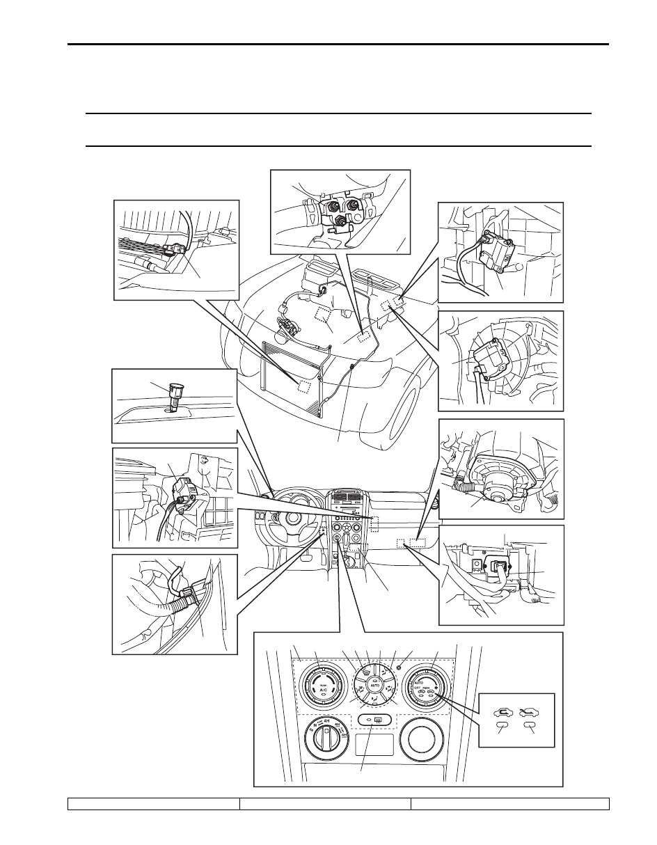
Component Location

A/C Control System Components Location

S5JB0B7203002

NOTE
The figure shows left-hand steering vehicle. For right-hand vehicle, parts with (*) are installed at the 
opposite side.


1

*2

*7

*3

*6

*11

*10

9

8

4

5

22

23

27

25

12

24 26

14

16

15

21

13

17

19

18

20

I5JB0B720004-04

1. Outside temperature sensor

10. Blower motor

19. Theft deterrent light

7B-7 Air Conditioning System: 

Diagnostic Information and Procedures

Scan Tool Data

S5JB0B7204006

As the data values given below are standard values estimated on the basis of values obtained from the normally 
operating vehicles by using a scan tool, use them as reference values. Even when the vehicles are in good condition, 
there may be cases where the checked values do not fall within each specifies data range. Therefore, judgement as 
abnormal should not be made by checking with these data alone.

2. Sunload sensor

11. Blower motor controller

20. Blower speed selector / Air intake selector

3. Inside temperature sensor

12. Temperature selector / A/C switch

21. Rear defogger switch

4. ECT sensor

13. “DEF” switch

22. “REC” indicator lamp

5. Refrigerant pressure sensor

14. “DEF / FOOT” switch

23. “FRE” indicator lamp

6. Evaporator temperature sensor

15. “FOOT” switch

24. MODE selector

7. Air intake control actuator

16. “BI-LEVEL” switch

25. HVAC control module (vehicle with A/C)

8. Temperature control actuator

17. “VENT” switch

26. “DEF” indicator lamp

9. Air flow control actuator

18. “AUTO” switch

27. Additional heater assembly

Scan Tool Data

Condition

Normal Condition / 

Reference Value

)

 TEMP CONT SWITCH

Each reference value is relative to the position of 
temperature selector of HVAC control module.

Max Cool, 18 

°C (61 °F) – 

28 

°C (81 °F), Max Hot

)

 CABIN TEMPERATURE

Reference value is relative to in car temperature.

–40 

°C – 87.5 °C

(–40 

°F – 189.5 °F) 

)

 OUT SIDE AIR TEMP

Reference value is relative to outside air temperature.

–40 

°C – 87.5 °C

(–40 

°F – 189.5 °F)

)

 EVAPORATOR TEMP

Reference value is relative to temperature of evaporator.

–40 

°C – 87.5 °C

(–40 

°F – 189.5 °F) 

)

 COOLANT TEMP

At specified idle speed after warming up

–40 

°C – 215 °C

(–40 

°F – 419 °F)

)

 SUN LOAD

Reference value depends on the situation.

0 W/m

2

 – 4447.8 W/m

2

)

 MODE CONT SWITCH

Each reference value is relative to the position of airflow 
selector of HVAC control module.

AUTO, VENT, BI-LEVEL, 

FOOT, DEF-FOOT DEF

)

 FAN CONT SWITCH

Each reference value is relative to the position of blower 
speed selector of HVAC control module.

AUTO, OFF 1st, 2nd – 7th, 

8th

)

 FAN DESIRE VOLT

Reference value is relative to the position of blower 
speed selector of HVAC control module.

0 – 16.0 V

)

 AIR MIX POS SENSOR

Reference value is relative to the position of temperature 
selector of HVAC control module.

Approx. 1.5 V (Max Hot)

Approx. 4.5 V (Max Cool)

)

 R/F POS SENSOR

Reference value is relative to the position of air intake 
selector of HVAC control module. (LH steering vehicle)

Approx. 4.0 V (REC)

Approx. 0.9 V (FRE)

)

 R/F POS SENSER

Reference value is relative to the position of air intake 
selector of HVAC control module. (RH steering vehicle)

Approx. 0.9 V (REC)

Approx. 4.0 V (FRE)

)

 MODE POS SENSOR

Reference value is relative to the position of airflow 
selector of HVAC control module.

Approx. 0.5 V (DEF)

Approx. 4.5 V (VENT)

)

 A/C CONT SIG

A/C system is ON.

ON

A/C system is OFF.

OFF

)

 AIR INTAKE MODE

Fresh air (FRE) mode is activated.

FRE

Recirculation air (REC) mode is activated.

REC

AUTO mode is activated.

AUTO

)

 A/C COMP CLUCH

Magnet clutch is engaged.

ON

Magnet clutch is not engaged.

OFF

)

 REFRIGERANT PRESSURE

Engine 
running.

A/C system is ON (compressor is operating) at 
ambient temperature: 30 

°C (86 °F)

For more details, refer to 

pressure of high pressure 

gauge under “A/C System 

Performance Inspection”.

A/C system is ON (compressor is not 
operating) at ambient temperature: 30 

°C (86 

°F) and engine coolant temperature: 90 °C – 
100 

°C (194 °F – 212 °F)

600 – 1000 kPa after 

longer than 10 min from A/

C switch turned off.

Air Conditioning System:  7B-8

Scan Tool Data Definitions
TEMP CONT SWITCH:  
Position of temperature control 

selector of HVAC control module

CABIN TEMPERATURE:  In-car temperature detected 

by inside air temperature sensor installed in HVAC 
control module

OUTSIDE AIR TEMP (OUTSIDE AIR 

TEMPERATURE):  Outside air temperature 
detected by outside air temperature sensor installed 
in front bumper member

EVAPORATOR TEMP:  Temperature of air passed 

through evaporator

COOLANT TEMP:  Engine coolant temperature 

detected by engine coolant temperature sensor

SUN LOAD:  Amount of sunlight detected by sunload 

sensor installed on the driver side on the dashboard

MODE CONT SWITCH:  Position of airflow selector of 

HVAC control module

FAN CONT SWITCH:  Position of air speed selector of 

HVAC control module

FAN DESIRE VOLT:  Voltage for blower motor
AIR MIX POS SENSOR:  Input signal from position 

sensor in temperature control actuator

MODE POS SENSOR:  Input signal form position 

sensor in air flow control actuator

R/F POS SENSOR (AIR FLOW CONTROL ACTUATOR 

POSITION SENSOR):  Input signal from position 
sensor in air intake control actuator

A/C CONT SIG (ON or OFF):  State of A/C indicator 

lamp

AIR INTAKE MODE (FRE, REC or MIX):  State of air 

intake mode 

A/C COMP CLUCH:  State of magnet clutch

REFRIGERANT PRESSURE (A/C REFRIGERANT 

ABSOLUTE PRESSURE):  This parameter 
indicates A/C refrigerant absolute pressure 
calculated by ECM

A/C INDICATOR LAMP (ON or OFF):  State of A/C 

indicator lamp

FRE INDICATOR LAMP (ON or OFF):  State of fresh air 

(FRE) indicator lamp

REC INDICATOR LAMP (ON or OFF):  State of 

recirculation air (REC) indicator lamp

REAR DEF INDICATOR (ON or OFF):  State of rear 

defogger indicator lamp

VEHICLE SPEED:  This parameter indicates vehicle 

speed calculated by BCM.

ENGINE SPEED:  This parameter indicates engine 

speed calculated by ECM.

SUPPLEMENT HT 1 (ON or OFF):  State of additional 

heater relay No. 1

SUPPLEMENT HT 2 (ON or OFF):  State of additional 

heater relay No. 2

SUPPLEMENT HT 3 (ON or OFF):  State of additional 

heater relay No. 3

)

 A/C INDICATOR LAMP

A/C indicator lamp is lighted.

ON

A/C indicator lamp is not lighted.

OFF

)

 FRE INDICATOR LAMP

Fresh air (FRE) indicator lamp is lighted.

ON

Fresh air (FRE) indicator lamp is not lighted.

OFF

)

 REC INDICATOR LAMP

Recirculation air (REC) indicator lamp is lighted.

ON

Recirculation air (REC) indicator lamp is not lighted.

OFF

)

 REAR DEF INDICATOR

Rear defogger indicator lamp is lighted.

ON

Rear defogger indicator lamp is not lighted.

OFF

)

 SUPPLEMENT HT 1

Additional heater relay No.1 is ON.

ON

Additional heater relay No.1 is OFF.

OFF

)

 SUPPLEMENT HT 2

Additional heater relay No.2 is ON.

ON

Additional heater relay No.2 is OFF.

OFF

)

 SUPPLEMENT HT 3

Additional heater relay No.3 is ON.

ON

Additional heater relay No.3 is OFF.

OFF

)

 VEHICLE SPEED

Vehicle stops.

0 km/h (0 mph)

)

 ENGINE SPEED

Engine is running at idle.

Engine idle speed is 

display

Scan Tool Data

Condition

Normal Condition / 

Reference Value

7B-9 Air Conditioning System: 

A/C System Performance Inspection

S5JB0B7204008

1) Confirm that vehicle and environmental conditions 

are as follows. 
• Vehicle is put indoors. 
• Ambient air temperature is within 15 – 35 

°C (59 – 

95 

°F).

• Relative humidity is within 30 – 70%.
• There is no wind indoors.
• HVAC unit is normal condition.
• There is no air leakage from air ducts.
• Condenser fins are clean.
• Are filter is not clogged with dirt and dust.
• Battery voltage is 12 V or more.
• Radiator cooling fan operates normally.

2) Make sure that high pressure valve (1) and low 

pressure valve (2) of manifold gauge (3) are firmly 
closed.

3) Connect high pressure charging hose (4) to high 

pressure service valve (5) on vehicle, and connect 
low pressure charging hose (6) to low pressure 
service valve (7) on vehicle.

4) Bleed the air in charging hoses by loosening their 

respective nuts on manifold gauge, utilizing the 
refrigerant pressure. When a hiss is heard, 
immediately tighten nut.

WARNING

!


Make sure to connect high and low pressure 
charging hoses to correct valves. Connecting 
them in the other way around may cause 
charging hoses and refrigerant container to 
burst.


5) Warm up engine to normal operating temperature 

(engine coolant temperature at 80 – 90 

°C (176 – 

194 

°F)) and keep it at specified idle speed.

6) Operate A/C at the following conditions.

• A/C switch at ON position
• Blower speed selector at max position
• Air flow selector at “VENT” position
• Temperature selector at max cool position
• Vehicle door at all open
• Air inlet door at recirculation position

7) Wait for ten minutes to stabilize A/C operation.
8) Keep all windows, doors and engine food open.
9) With about 20 mm (0.8 in.) of dry bulb thermometer 

(1) put right in front of center ventilation louver and a 
wet and dry bulb thermometer (2) near air inlet (3) of 
HVAC unit.

3

4

7

5

1

2

6

I5JB0B720005-02

1

3

2

I5JB0A720011-01


Content   ..  123  124  125  126   ..