Suzuki Grand Vitara JB416 / JB420. Manual - part 134


  Index      Suzuki     Suzuki Grand Vitara JB416 / JB420- service repair manual


Search            


Content   ..  132  133  134  135   ..


Suzuki Grand Vitara JB416 / JB420. Manual - part 134


1I-4 Starting System: 

Starting Motor Performance Test

S5JB0A1904002

CAUTION

!


Each test must be performed within 3 – 5 
seconds to avoid coil from burning.


Pull-In Test

1) Connect battery to magnetic switch as shown.
2) Check that plunger and pinion move outward. If 

plunger and pinion don’t move, replace magnetic 
switch.

NOTE
Before testing, disconnect lead wire from 
terminal “M”.


Hold-In Test

1) While connected as above with plunger out, 

disconnect negative lead (2) from terminal “M” (1).

2) Check that plunger and pinion remain out. If plunger 

and pinion return inward, replace magnetic switch.

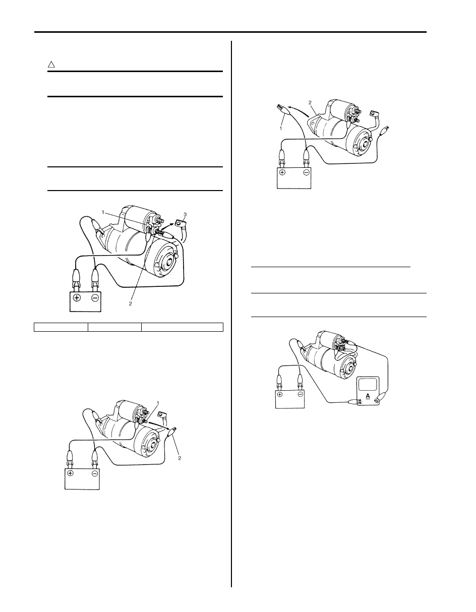
Plunger and Pinion Return Test

1) Disconnect negative lead (1) from switch body (2).
2) Check that plunger and pinion return inward. If 

plunger and pinion don’t return, replace the magnetic 
switch.

No-Load Performance Test

1) Connect battery and ammeter to starter as shown.
2) Check that starter rotates smoothly and steadily with 

pinion moving out. Check that ammeter indicates 
specified current.

Specified current (no-load performance test)
90 A MAX. at 11 V

NOTE
Use wires as thick as possible and tighten 
each terminal fully.


1. Terminal “S”

2. Terminal “M”

3. Lead wire (switch to motor)

IYSQ01190003-01

IYSQ01190004-01

IYSQ01190005-01

IYSQ01190006-01

Starting System:  1I-5

Repair Instructions

Starting Motor Dismounting and Remounting

S5JB0A1906001

Dismounting

1) Disconnect negative (–) battery lead at battery.
2) Hoist vehicle
3) Disconnect magnetic switch lead wire (1) and battery cable (2) from starting motor terminals.
4) Remove starting motor mount bolts (3).
5) Remove starting motor (4).

Remounting
Reverse the dismounting procedure noting the following.
• Tighten battery cable nut (5) to specified torque.

Tightening torque
Starting motor battery cable nut (a):  11 N·m (1.1 kgf-m, 8.0 lb-ft)

(a)

(c)

(a)

(b)

(b)

[A]

[B]

3

3

4

5

4

5

2

1

3

1

2

I5JB0A190001-02

[A]: For M16 Engine

: 11 N

⋅m (1.1 kgf-m, 8.0 lb-ft)

: 55 N

⋅m (5.5 kgf-m, 40.0 lb-ft)

[B]: For J20 Engine

: 25 N

⋅m (2.5 kgf-m, 18.5 lb-ft)

1I-6 Starting System: 

Starting Motor Components

S5JB0A1906005

The starting motor consists of parts shown in below and has permanent magnets mounted in starting motor yoke 
(frame).
The magnetic switch assembly and parts in the starting motor are enclosed in the housings so that they will be 
protected against possible dirt and water splash.

NOTE
Spare parts have been lubricated.


I5JB0A190002-01

1. Front housing

7. Plate

13. Planetary gear

19. Rear bush

2. Bush

8. Seal rubber

14. Packing

: 11 N

⋅m (1.1 kgf-m, 8.0 lb-ft)

3. Pinion stop ring

9. Magnetic switch

15. Yoke

: Do not reuse.

4. Over-running clutch

10. Starting motor battery cable nut

16. Armature

: Apply grease 99000-25010 to sliding surface of each part.

5. Lever

11. Internal gear

17. Brush assembly

6. Plunger

12. Planetary carrier shaft

18. Rear bracket

Starting System:  1I-7

Starting Motor Inspection

S5JB0A1906004

Plunger
Inspect plunger for wear. Replace if necessary.

Magnetic Switch
Push in plunger and release it. The plunger should 
return quickly to its original position. Replace if 
necessary.

Pull-In coil open circuit test

Check for continuity across magnetic switch “S” terminal 
and “M” terminal. If no continuity exists, coil is open and 
should be replaced.

Hold-In coil open circuit test
Check for continuity across magnetic switch “S” terminal 
and coil case. If no continuity exists, coil is open and 
should be replaced.

Rear Bracket Bush
Inspect bush for wear or damage. Replace if necessary.

Brush
• Check brushes for wear.

Measure length of brushes and if below the limit, 
replace the brush.

Brush length
Standard: 12.3 mm (0.48 in.)
Limit: 5.5 mm (0.22 in.)

• Install brushes to each brush holder and check for 

smooth movement.

IYSQ01190027-01

IYSQ01190028-01

IYSQ01190029-01

IYSQ01190030-01

IYSQ01190031-01

IYSQ01190032-01


Content   ..  132  133  134  135   ..