Suzuki Grand Vitara JB416 / JB420. Manual - part 35
1A-89 Engine General Information and Diagnosis:
3
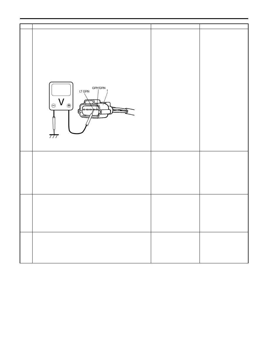
ECM voltage check
1) Disconnect connector from MAF and IAT sensor with
ignition switch turned OFF.
2) Check for proper connection to MAF and IAT sensor at
“LT GRN” and “GRY/GRN” wire terminals.
3) If OK, then turn ON ignition switch, measure voltage
between “LT GRN” wire terminal of MAF and IAT sensor
connector (1) and vehicle body ground.
Is voltage about 4 – 6 V?
Go to Step 6.
Go to Step 4.
4
IAT short circuit check
1) Disconnect connectors from ECM with ignition switch
turned OFF.
2) Measure resistance between “LT GRN” wire terminal of
MAF and IAT sensor connector and vehicle body
ground.
Is resistance infinity?
Go to Step 5.
“LT GRN” wire is
shorted to ground
circuit.
If wire is OK, substitute
a known-good ECM and
recheck.
5
IAT short circuit check
1) Turn ON ignition switch.
2) Measure voltage between “LT GRN” wire terminal of
MAF and IAT sensor connector and vehicle body
ground.
Is voltage about 0 V?
Go to Step 6.
“LT GRN” wire is
shorted to other circuit.
If wire is OK, substitute
a known-good ECM and
recheck.
6
IAT sensor for performance check
1) Check IAT sensor according to “Mass Air Flow (MAF)
and Intake Air Temperature (IAT) Sensor Inspection in
Section 1C”.
Is it in good condition?
Substitute a known-
good ECM and recheck.
Replace MAF and IAT
sensor.
Step
Action
Yes
No
I5JB0A110037-02