Suzuki Grand Vitara JB416 / JB420. Manual - part 16
1A-13 Engine General Information and Diagnosis:
Electronic Control System Description
S5JB0A1101007
The electronic control system consists of 1) various sensors which detect the state of engine and driving conditions, 2)
ECM which controls various devices according to the signals from the sensors and 3) various controlled devices.
Functionally, it is divided into the following sub systems:
• Fuel injection control system
• Ignition control system
• Intake manifold tuning valve control system (for J20 engine)
• Electric Throttle Body Control System
• Fuel pump control system
• Radiator cooling fan control system
• Evaporative emission control system (if equipped)
• EGR system
• A/F sensor heater control system (if equipped)
• Oxygen sensor heater control system (if equipped)
• A/C control system (if equipped with A/C)
• Camshaft position control system (for M16 engine)
• Immobilizer control system (if equipped)
• Generator control system (for J20 engine)
• Controller (computer) communication system
Especially, ECM (Engine Control Module), BCM (Body electrical Control Module), combination meter, TCM
(Transmission Control Module (For A/T model)), ABS hydraulic unit / control module assembly, 4WD control module
(for J20 engine) and keyless start control module (if equipped) intercommunicate by means of CAN (Controller Area
Network) communication.
Refer to “Engine and Emission Control System Flow Diagram” and “ECM Input / Output Circuit Diagram”.
AFS-
AFRV
AFRG
AFH+
AFH-
AFS+
5V
5V
12V
1
1
3
7
8
2
8
9
10
5
11
12
13
14
15
4
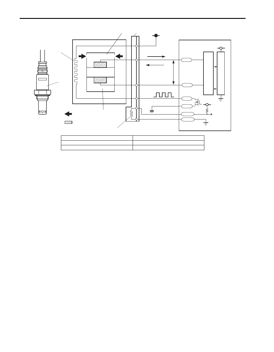
I5JB0A110010-02
10. Electrode 13. Lean
11. A/F signal processing circuit
14. Rich
12. CPU 15. 0.4
V