Dacia SuperNova (engine E7J). Manual - part 117


  Index      Dacia     Dacia SuperNova (engine E7J) - service repair manual 2004 year


Search            


Content   ..  115  116  117  118   ..


Dacia SuperNova (engine E7J). Manual - part 117


82A

HORN - ENGINE IMMOBILISER

82A - 1

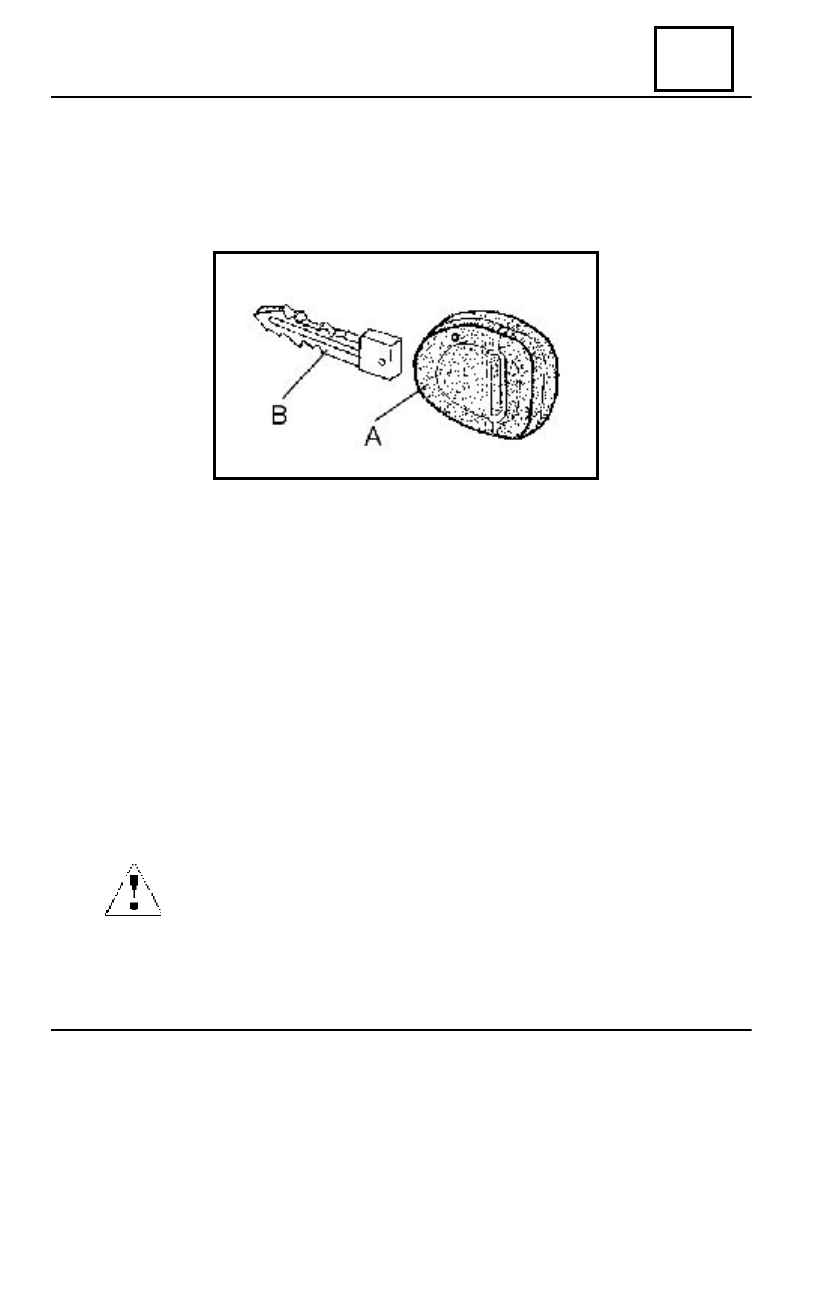
This type of anti starting system is based on the key recognition, which has a special construction.

It may be separated in two elements which can be identified in the following way (pict.1): the key
head (pos.A.) made of plastic, which can be dismounted and the metal insertion (pos.B.), which is
fixed and ensured by clipping in the key head.

In the key head, there is a coded independent electronic circuit, which is functioning without

battery. When setting the contact on, the anti starting bushing, placed around the starting contact,
is enquiring and catching the coded signal emitted by the key head, then sends it to the Electronic
Control Unit (E.C.U.)  decoder. This one is attached on  the front left pillar, under the lower casing
of the dashboard and has the function of receiving the code sent from the bushing. If the decoder
recognises the key code then it will send a coded signal to the injection computer, which compares
it with the previous memorised code and will authorise or not the start of the engine.

We mention that the system with radio frequency remote control (RF) of the doors blocking

/unlocking, has no influence to the anti starting system. In this case, the key head has a different
construction, having an activation button of the remote control and a red LED, which is lighted in
the moment of blocking/unlocking the  doors, by pushing the key button. Inside the key head
there is the coded electronic circuit for the anti starting system and an imprinted electronic circuit,
supplied by a battery, for the RF remote control operation of blocking/unlocking the vehicle
doors.

The anti starting system is activated after approximate 10 seconds from the breaking of the

contact and is visualised by the blinking of the anti  starting indicator placed on the instrument
panel.

If the battery is low charged, the tension drop on the starter, at starting,

may cause the activation of the anti starting system and the start of the engine is
impossible.

      pict.1

GENERALITIES

ATTENTION

82A

HORN - ENGINE IMMOBILISER

82A - 2

ATTENTION 

After dismounting the key head, it is forbidden to touch the electric circuit located

inside of it, as this can cause the further non-operation of the anti starting system and
impose a replacement of the key head.

The key head has marked inside, a number of identification, formed by 8 alphanumeric

characters (letters and figures) and this one is mentioned on the vehicle’s invoice.

If the replacement of the battery from the key head is necessary, this can be opened in the

following way :

- keep the key in horizontal position, the half with the metal insertion being downwards ;
- with a little screwdriver, positioned as in the picture (picture2), act upon the key head in

the direction indicated by the arrow, in order to begin the dismounting.

- move carefully the upper side of the key in the direction indicated by the arrow (picture 3)

and then the two parts of the key will separate.

If the replacement of the metal insertion ( the mechanical part) of the key is needed, proceed as follows:

- open the key head according to the a.m. procedure  ;
- unlock carefully the  maintaining claw (picture 4, pos.C) of the metal insertion (B).
- remove the metal insertion by sliding from the key head.

Introduce by sliding the new metal insertion until a  « click » is heard, which confirms its

attachment on the key head.

pict.2

pict.3

pict.4

GENERALITIES

THE KEY HEADS

82A

HORN - ENGINE IMMOBILISER

82A - 3

GENERALITIES

The anti starting bushing (picture 5) is located around the starting contact and is accessible

after the dismounting the steering wheel’s cases. It catches the signal from the key head and then
sends a coded signal to the E.C.U. decoder.

The vehicles equipped with RF remote control keys for blocking/ unlocking the doors are

provided with another anti starting bushing which transmits to the E.C.U. decoder also the signal
received from  the RF remote control.

The recognition of the two types of decoding bushings is realised by means of codes labelled

on their body, as follows :

- code 042264J

- for vehicles without RF remote control

- code  8200044257

- for vehicles with RF remote control

The  E.C.U. decoder (picture 6) has the

following functions :

- decode the signal received from the anti

starting bushing ;

- sends a code to the injection computer

in order to authorise the engine starting.

- controls the anti starting indicator of the

instrument panel

- receives the coded signal from the anti

NOTE 
In case both keys were lost, the code of the key head (8 characters) and the code of

the metal insertion (4 characters) can be red from the vehicle invoice. If also the invoice
was lost, the two mentioned codes can be found out based on the chassis series number
of that vehicle, accessing the database of the DACIA manufacturer, calling the TECH
LINE.

pict.5

pict.6

starting bearings, for the vehicles equipped with RF remote control;

- commands the blocking/unlocking of the doors, if the vehicle is provided with RF remote

control keys;

-


commands the dome ceiling lighting, for the vehicles equipped with this system

.

E.C.U. DECODER

ANTI STARTING BUSHING

82A

HORN - ENGINE IMMOBILISER

82A - 4

NOTE :

The vehicles equipped with this anti starting system, have a type of decoder, and those
provided also with RF remote control for locking/ unlocking doors have another type
of decoder.
The identification of the two types of E.C.U. decoder is realised by the inscriptions on
the labels as follows:

- code P8200032783H and the inscription TRANS-PLAF for the vehicles without

RF remote control;

- code P8200032776H and the inscription TRF-TRANS-CAR for the vehicles

with RF remote control.

ANTI  STARTING INDICATOR

It is located on the instrument panel (picture 8, position A) and has the following functions:

- signals the activation of the anti starting system
- signals the case of non identifying the key head
- signals the entrance in the operation mode “resynchronisation” of the remote controls,

RF with E.C.U. decoder, for the vehicles which use the RF remote control.

pict.7

pict.8

   A

GENERALITIES

The dome ceiling lighting is activated subject to the position of the switch (picture 7, position 1):

- position A   the ceiling lights permanently
- position B   the ceiling turned off
- position C   dome ceiling lighting; this will light for 5 seconds after a front door closing or

after the command of unlocking the doors with the RF remote control. This delay turns out in the
moment of  setting the contact.


Content   ..  115  116  117  118   ..