Dacia Solenza (engine E7J). Manual - part 174


  Index      Dacia     Dacia Solenza (engine E7J) - service repair manual 2004 year


Search            


Content   ..  172  173  174  175   ..


Dacia Solenza (engine E7J). Manual - part 174


88

WIRING

88 - 25

DISMOUNTING

Disconnect the battery (-) terminal.
Detach from  clips the  crane  handle.
Dsimount the rear door panel (see chapter 72 “ Rear door panel”).
Dismount the rear door deflective panel.
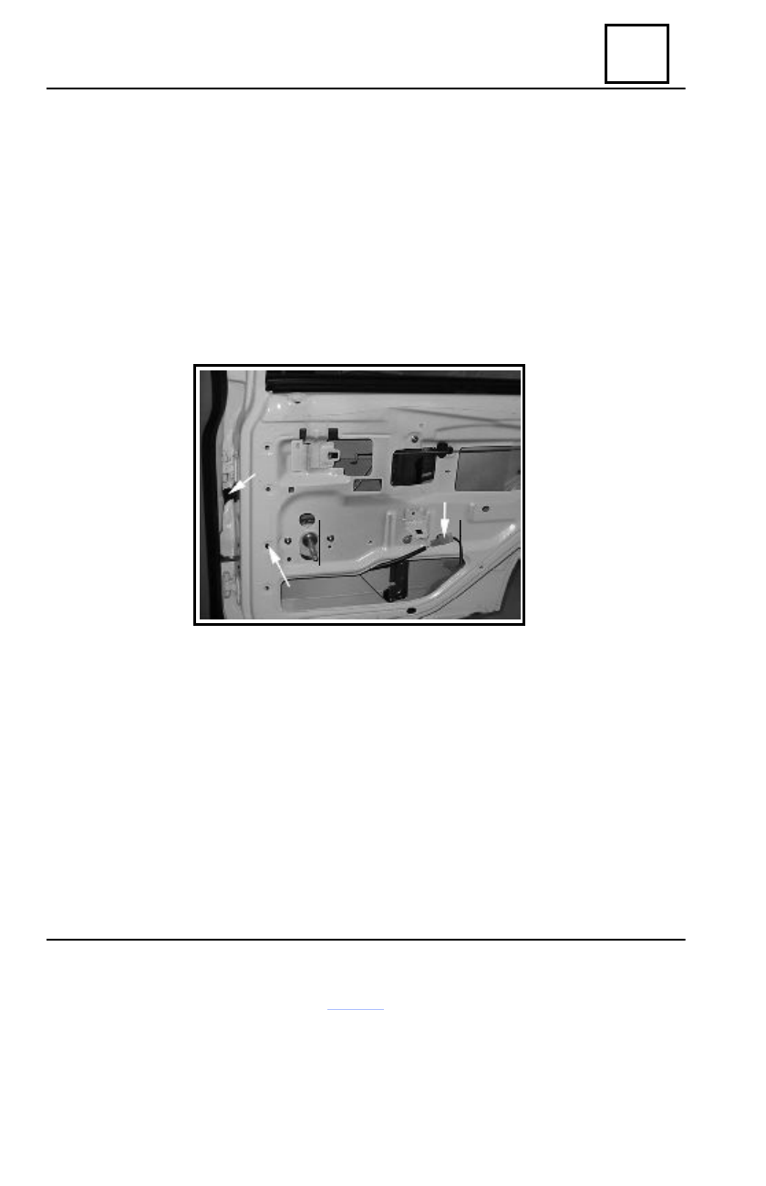
Dismount the attachment clip (1) of the rear wiring.
Disconnect and detach from clips actuator’s  connector (2).
Remove the wiring protector (3) from the rear door and middle pillar. Mark the mounting

position of  the protector.

Remove the rear wiring from the door. Mark the mounting position of the rear wiring.
Carefully remove protector off the wiring

1

2

3

Rear door wiring protector

REMOUNTING

Perform the dismounting operations in the reverse order, observing the mounting position

previously existent.

Replace the attachment clip (1).
Check the actuator’s operation and windows’ operation.

89

ELECTRIC DIAGRAMS

89 - 1

GENERAL PRESENTATION

From electric point of view, the vehicle electric diagrams have been structured as Applied Principle
Schemes (APS), presented according to each system function. These APS diagrams also contain
details concerning the internal function of some simple electric components (contacts, relays), thus
contributing to a better understanding of the system functioning and of the incident good diagnosis.

 Chapter 2 includes the list of the vehicle functional diagrams (APS). They are divided in

electric’s supply diagrams, mass connection diagrams and  system functional diagrams.

Chapter 7 includes the electric functional diagrams (APS), identified as follows:

- electric components marked by 3-4 figures; their identification on the electric diagrams

can be achieved by means of “Index of components” – see Chapter 3;

- connections between the  electric  wiring,  marked by  an  “R”  followed by  figures; they  are

indicated in  the  Chapter 4  list;

- mass connections, marked by an M followed by figures or letters; they are indicated in

Chapter 4.

Every wire of the electric diagrams is defined by an alphanumeric code representing its function,

followed by a group of letters, representing the color of that wire.

Chapter 11  includes the  connectors  and connections between wiring,  drawn from the  later inlet

towards the connector/connection. The wires entering each connector socket are identified by
means of  the above-mentioned  drawings. The Chapter 11 also includes detailed tables about each
wire entering the connector: wire location in the connector socket, wire section, wire function
code and its destination.

Chapter 11 includes the index of all wire functions in connectors and connections, namely the

list of  all the connectors and  connections, which helps to their easy identification in Chapter 11.

Chapter 5 includes the mass and connection positions on vehicle and helps to identify the

electric mass fixing points on it, as well as location of the connections between its wiring.

Chapter 6 includes the electric component position on vehicle. The location of the various

components with electric functions on the vehicle can be identified by means of the component list.

The cockpit fuse box is presented in Chapter 8 and contains information about its positioning

and the functional purpose of the fuse.

General

89

ELECTRIC DIAGRAMS

89 - 2

The fuse box from the engine compartment is presented in Chapter 9, that contains information

about its location on the vehicle and the functional purpose of the relays and fuse placed on it.

The functional codes of the wires are detailed explained in Chapter 12.

FUNCTIONAL DIAGRAMS INTERPRETATION

The functional diagram information included in Chapter 7 are to be interpreted taking into

consideration the explanation referring to the following example:

1 = vehicle class
2 = manufacturing year
3 = functional electric diagram denomination
4 = equipment differentiation criteria for identifying the functional electric diagram ˙
5 = electric connector colour ˝
6 = connector graphical representation
7 = electric component index number
8 = number of the fuse box on which the relay or safety fuse is mounted
9 = safety fuse identification on fuse box

10 = safety fuse value
11 = identification of wiring joints
12 = electric mass identification
13 = electric connection colour between wiring ˝
14 = electric connection identification
15 = electric connection graphical representation
16 = symbol, pages containing functional diagrams
17 = wire function code
18 = wire colour ˝
19 = functional diagram number

OBSERVATION:
1. The area (4) specifies the differentiating elements serving to the various functional diagrams

identification, considering the following symbols:

ABCO01 = driver’s airbag

CA = climate maintenance with air conditioning
CHAUFO = climate maintenance without air conditioning
CPE = Electric locking/unlocking doors control
DA


= assisted power steering

E0, E1, E2


= levels of  equipment

LVE


= front windows electric control

______________________________________________________________________________

General

89

ELECTRIC DIAGRAMS

89 - 3

MA = motorization in agreement with the  EURO 96 (EURO II) de-pollution norm
MB = motorization according to the EURO 2000 (EURO III) de-pollution norm
PROJAB = fog projectors
RAD01


= Front loud speaker radio-cassette  player

RAD02


= Rear loud speaker radio-cassette player

RAD03


= Front and rear loud speaker radio-CD player

TLAIF1


= Countries group definition


(SASO norms)

2. The electric connectors (5), couplings (13) and wires (18) are symbolised by the following

colours:

BA = white

JA = yellow

SA = pink- salmon

BE = blue

MA = brown

VE = green

BJ =  beige

NO = black

VI = violet

CY = white-crystal

OR = orange

GR = grey

RG = red

General


Content   ..  172  173  174  175   ..