Dacia Solenza (engine E7J). Manual - part 154


  Index      Dacia     Dacia Solenza (engine E7J) - service repair manual 2004 year


Search            


Content   ..  152  153  154  155   ..


Dacia Solenza (engine E7J). Manual - part 154


84

STEERING - CONNECTOR

84 - 1

ANTI-THEFT MECHANISM

(IGNITION-STARTING SWITCH)

The anti theft mechanism is placed on the right part of the steering column and has the purpose

to starter control, electric system connecting and disconnecting, being provided in the same time
also with a steering locking  device, with anti theft lock.

DISMOUNTING

Disconnect the battery (-) terminal
Dismount the 3 TORX 20 attachment screws of the steering wheel half-casings.
Detach from  clips the  steering  wheel casings  and  remove  them.
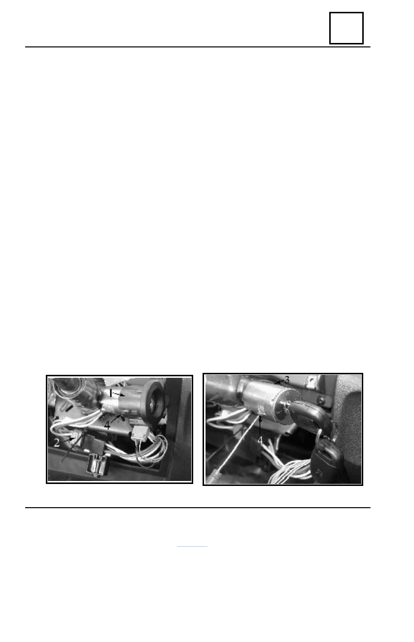
Disconnect the anti-starting bushing connector
Remove the anti-starting bushing (1) located around the anti-theft mechanism.
Disconnect the connectors (2) of the anti-theft mechanism.
Dismount the attachment screw (3) of the anti-theft mechanism by means of a screwdriver.
Bring the key on the position and push the mobile retaining pin (4) and releasing of the anti-

theft mechanism.

Extract the mechanism towards backwards.

REMOUNTING

Position the contact key in the bellow position and push the mobile pin (4).
Mount the mechanism in its place, attaching it by means of the mobile pin and of the screw (3).
Connect (2) the anti-theft mechanism connectors.
Position and mount the anti-starting bushing (1) around the anti-theft mechanism.
Connect the anti starting bushing connector.
Mount the steering wheel half-casings.
Connect the battery (-) terminal.
Check the operation of the anti-theft mechanism.

Anti-theft mechanism

84

STEERING - CONNECTOR

84 - 2

The under steering wheel control assembly and the rotating contact included in this one, can not

be separated.

DISMOUNTING
Disconnect the battery (-) terminal.
Place the steering at the middle point (straight line driving position of the vehicle).
Detach from clips the steering wheel central ornament (cover).
Dismount the steering wheel attachment screw.
Carefully dismount the steering wheel in order not to damage “the tape connector” of the

rotating contact; ensure that wheels are in the straight line driving position of the vehicle.

Dismount the TORX 20 three attachment screws of the steering wheel half-casing.
Detach from clips the steering wheel half-casings and remove them.
Disconnect the windscreen wiper switch connector and the connector of the turning and lighting

control switch.

Loosen the screw (1), unblocking the under steering wheel control assembly from the attach-

ment cone of the steering column.

Extract the under steering wheel control assembly from the attachment cone of the steering

column.

REMOUNTING
Ensure that wheels are in the straight line driving position of the vehicle.
Position the under steering wheel control assembly so that after mounting the two steering

wheel half-casings, the assembly handles are lined up with the instrument panel and the dashboard.

Reconnect the windscreen wiper connector and the connector of the turning and lighting control

switch.

Attach in clips the steering wheel half-casings. Mount their attachment screws.
Tighten the screw (1) in order to block the under steering wheel control assembly on the steer-

ing column. This operation is facilitated by a cutout in the lower half-casing, enabling access to the
screw (1).

Carefully mount the steering wheel in order not to damage “the tape conector” of the rotating

contact; the steering wheel has an area without grooves on the steering column. Steering wheel
must easy enter in grooves.

Replace the steering wheel attachment screw (TORX 50) after each dismounting ( pre-glued

screw) and tighten it (required tightening moment 4.4 daNm). Attach in clips the steering wheel
central cover.

Reconnect the battery (-) terminal.
Check the operation of the under steering wheel control.

Under steering wheel control

1

84

STEERING - CONNECTOR

84 - 3

Under steering  wheel  control

The under steering control assembly and the rotating contact included in this one are not to be

separated. The rotating contact is ensuring the electric connection between the steering column
and the steering wheel. This contact is connected with the from wiring by means of  wires stacked
as tape-shaped having the necessary length provided to ensure 5 steering wheel rotations (limited
by the wheels camber plus one more for safety).

DISMOUNTING

ATTENTION !
It is forbidden the handling of the pyrotechnic system (airbag) near heating sources

or open fire, because there is a risk of undesirable starting of the system.

IMPORTANT !
Anytime when dismounting the steering wheel,  it is necessary to  dismount the  airbag

connector (1). The airbag is provided with a connector who is short-circuited after
disconnecting the wiring connector, avoiding in this way all undesirable starting.

Block the UCE airbag by means of the CLIP tester (see chapter 88 “ UCE airbag blocking”).

The airbag indicator from the instrument panel is on.

Disconnect the battery (-) terminal.
Set the steering on the middle point (straight on driving position of the vehicle).
Dismount the two attachment screws TORX 20 of the airbag to the steering wheel.
Dismount the airbag connector (1).
Dismount the steering wheel attachment screw.
Carefully dismount the steering wheel for not damaging the “tape” connector of the rotating

contact; ensure  that wheels are in straight-on vehicle driving position.

Dismount the three attachment screws TORX 20 of the steering wheel half-cases.
Detach from clips the steering wheel half-cases and remove them.
Disconnect the windscreen wiper connector, the lights and turning control connector and the

rotating contact connector.

Loosen the screw (2) unblocking in this way the under steering wheel control assembly from

the attachment cone of the steering column.

Extract the under steering wheel control  assembly off the attachment cone of the steering column.
ATTENTION !
It is forbidden the changing of the rotating contact position after dismounting the

under steering wheel control assembly because there is the risk of its damaging.

The under steering wheel control – new item number- is provided with a pre-cut

self-adhesive tape, stacked on the rotating contact and on the under steering wheel
control body that is not allowing the undesirable rotation of the rotating contact until
its mounting on the attachment cone of the steering column.

1

2

84

STEERING - CONNECTOR

84 - 4

Under steering wheel control

REMOUNTING

Ensure that steering is on middle point (wheels are in the straight-on driving position of the

vehicle).

Position the under-steering wheel control assembly so that after remounting the two steering

wheel half-cases, the assembly handles are lined up with the instrument panel and the dashboard.

Reconnect the windscreen wiper connector, the lights and turning connector and the rotating

contact connector.

Attach in  clips the  steering  wheel half-cases.
Tighten the screw  (2) so that is blocking the under-steering wheel control on the steering

column. This operation is facilitated by a cutting-out in the lower half-case allowing the access to
the screw (2).

Carefully mount the steering wheel in order not to damage the “tape” connector of the rotating

contact, the steering wheel is having an area with no grooves, that must be corresponding to the
no-grooves area from the steering column. The steering wheel must easy enter in the grooves.

Replace the steering wheel attachment screw (TORX 50) after each dismounting and tighten

it to the required moment (4.4 daNm).

Reconnect the airbag  connector (10.
Mount the two attachment screws TORX 20 of the airbag (required tightening moment is

0.65 daNm)

Reconnect the battery  (-) terminal.
Check the operation of the under steering weel control.
IMPORTANT !
Before reconnecting the driver’s airbag connector, it is necessary to apply a check-

ing procedure of the system:

- check if the airbag indicator from the instrument panel is on, when the contact

is set on;

- connect the inert igniter to the airbag connector (to the wiring) and check if the

airbag indicator is off;

- set the contact off, connect the airbag connector instead of the inert igniter and

attach the airbag on the steering wheel (required tightening moment is 0.65 daNm).

ATTENTION !
Any doubts regarding a good centering of the rotating contact involves the applying

of its centering method: carefully rotate clockwise the upper part of the rotating con-
tact 2.5 complete rotations (or until it gets blocked), then rotate anti-clockwise 2.5
complete rotations.

In case of a steering dismounting operation, of the engine or of the transmission

elements implying the steering rack or steering column uncoupling, the steering wheel
must be immobilized.

After everything has been remounted, perform an airbag system checking by means

of the CLIP tester. If everything is correct, unblock the UCE airbag and check if the
airbag indicator from the instrument panel is on for 3 seconds from setting the contact
on, then it is off and is remaining off. If the airbag indicator is not operating as a.m.,
see chapter “Diagnostic” and check the system by means of the “CLIP” tester.

ATTENTION !
All non-observing of these prescriptions may cause an abnormal operation of the

system, even an undesirable starting of it.


Content   ..  152  153  154  155   ..