Dacia Solenza (engine E7J). Manual - part 135


  Index      Dacia     Dacia Solenza (engine E7J) - service repair manual 2004 year


Search            


Content   ..  133  134  135  136   ..


Dacia Solenza (engine E7J). Manual - part 135


81

INSIDE AND REAR LIGHTING

81 - 7

Lamps failures diagnostic

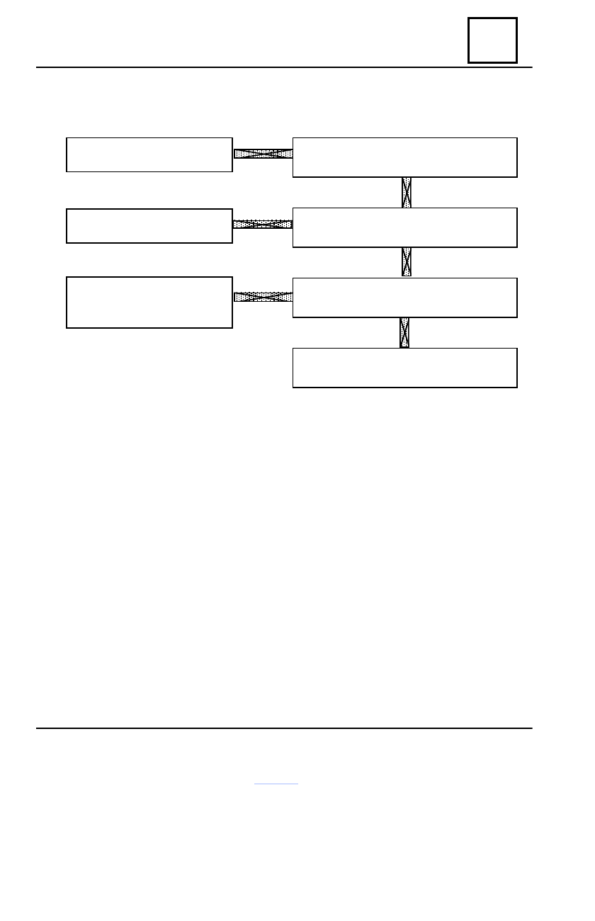
STOP LAMPS NOT WORKING

Check fuse F04 from cockpit fuse box.

Is it good?

Replace fuse  F04

Yes

Yes

No

No

No

Yes

Replace the  Stop  contact

The stop contact wire supply is

broken or disconnected.

Fix it.

Bridge the Stop contact terminals.

Are the lamps working?

Is the Stop contact supplied ?

The stop contact wire supply is broken or

disconnected. Fix it.

INSIDE AND REAR LIGHTING

81

81 - 8

DISMOUNTING

Disconnect the (-) plug of the battery.
Pull the seat (1) of the access flap (2) to the fuse box located in the cockpit, at the left end of

the dashboard. Carefully remove flap (2).

Dismount the attaching screws (3) of the fuse box on the driving post crossbeam and detach

it from clips (4)

REMOUNTING

Attach in clips  (4) the fuse box on the driving post crossbeam and mount the screws (3).
Carefully mount, the access flap (2) to the fuse box.
Connect the battery (-) terminal.
Perform functional tests, noticing the correct operation of  all consumers supplied by  means

of the cockpit fuse box.

OBSERVATION:

    For vehicle equipped with programmable radio-tape player and electronic clock, af-
ter battery reconnecting, the radio code must be introduced and the clock re-programmed.
    If COBRA 3800 or COBRA 3900 alarms have been mounted on the vehicle, in the
fuse box, may be found fuses F29 with value 15 A (mounted in seat (5)) and F 30 with
value 5A (mounted in seat (6)).

Cockpit fuse box

2

1

4

4

3

3

5

6

81

INSIDE AND REAR LIGHTING

81 - 9

Cockpit fuse box

The fuses are protecting the following electric circuits:

  Fuse      Symbol

Fuse

                                  Protected circuit

 number

type

F01

Free

F02

PLAF

15 A

Instrument panel, cockpit UCE(ceiling lamp operation, radio

F03

20 A

Cockpit UCE, air conditioning climate control panel *

F04

15 A

Cockpit UCE, diagnostic socket, airbag  UCE,  anti-starting

bushing

F05

UCE

10 A

UCE injection, petrol pump relay/ignition coil, instrument panel


INJECTION

F06

10 A

Windscreen wiper-washer  switch (windscreen washing pump

operation), reverse driving switch, STOP switch, air

conditioning climate control panel*

F07

20 A

Windscreen wiper-washer switch, UCE cockpit (windscreen
wiper timer operation), windscreen wiper motor (stopping at fix point).

F08

7,5 A

Left meeting lights, instrument panel (indicator)

F09

7,5 A

Right meeting lights

F10

7,5 A

Left road lights, instrument panel (indicator)

F11

7,5 A

Right road lights

F12

15 A

Acoustic warning

F13

25 A

UCE cockpit (turning lights and hazard), diagnostic socket.

F14

7,5 A

Front/rear left parking lights, lighting: switches, climate control

 panel, instrument panel, lighter, radio.

F15

7,5 A

Front/rear right parking lights

F16

15 A

Lighter, radio

F17

30 A

Climate control blower

F19

7,5 A

Fog lamp, instrument panel (indicator)

F20

25 A

Rear window defrosting

UCE

F21


INJECTION      

5 A

UCE injection

F23

30 A

Right/left electric window regulator switch

F26

30 A

Air conditioning climate control blower*

F28

20 A

Fog projectors

* for vehicles equipped with air  conditioning

INSIDE AND REAR LIGHTING

81

81 - 10

   DESCRIPTION OF THE OPERATION

Dismount the battery (-) terminal;
Dismount the access flap to the  cockpit fuse box;
Dismount the attachment screw of the UCE decoder and relays assembly.
Lift from its attachment place and remove UCE decoder and relays assembly.

UCE decoder protection

1

2

Carefully insert UCE decoder-relays assembly in the protector (1) so that protector is not

damaged.

Attach the protector to the front wiring by means of an attachment clip (2).
Mount the UCE decoder – relays assembly in the attachment  place.
Mount the attachment screw of the UCE decoder and relays assembly.
Mount the access flap of the cockpit fuse box.
Connect the battery (-) terminal.

ATTENTION!
At any intervention implying dismounting of the UCE decoder-relays assembly, the

protector and the attachment clip are to be replaced.


Content   ..  133  134  135  136   ..