Dacia Solenza (engine E7J). Manual - part 77


  Index      Dacia     Dacia Solenza (engine E7J) - service repair manual 2004 year


Search            


Content   ..  75  76  77  78   ..


Dacia Solenza (engine E7J). Manual - part 77


FRONT AXLES ELEMENTS

31

31 - 17

Shock absorber, Spring

TIGHTENING 

MOMENTS 

(daNm)

Shock absorber rod nut

6

Shock absorber lower attachment nut

10.5

Shock absorber upper attachment screws

2

The shock absorbers are stored in horizontal

position. In these conditions, it is possible that
shock absorbers working vertically, to get
depressed.

Therefore, before mounting on the vehicle, it

is necessary to perform the shock absorbers
pressing, by alternatively shifting the shock
absorber rod (upwards and downwards), the
shock absorber being in vertical position.
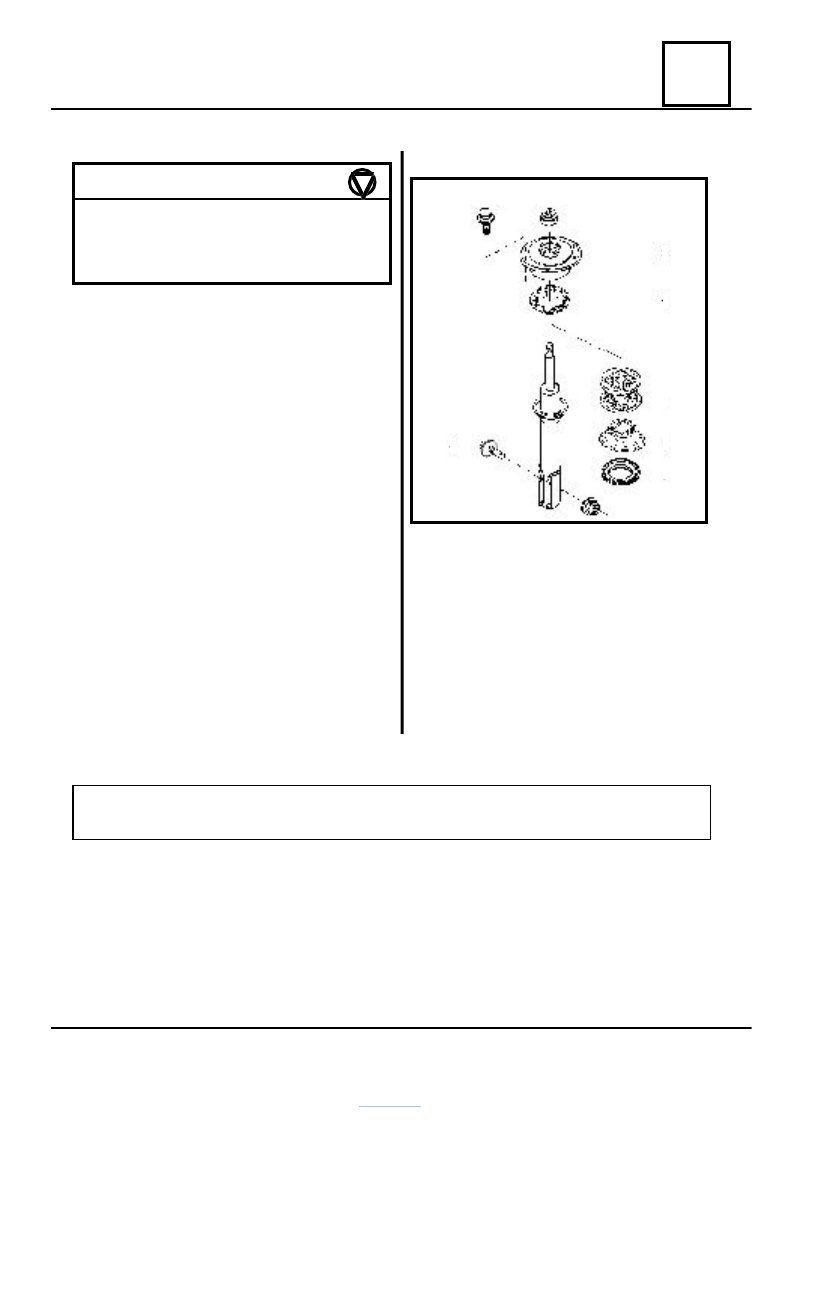
SHOCK ABSORBER

1. Upper attachment nut
2. Lower attachment screw
3. Filtering block
4. Upper plate
5. Shock buffer
6. Lower plate
7. Axial bearing

The coil diameter of the front axle spring is 

 Ø 13,1

+ 0,08


 mm.

REMARK :
Make sure that springs of every axle have the same characteristics.

- 0

3

4

5

6

7

2

1

FRONT AXLES ELEMENTS

31

31 - 18

Spring – shock absorber assembly

DISMOUNTING SPRING-SHO

CK ABSORBER 

ASSEMBLY

 OFF THE VEHICLE

Loosen the front wheel attachment screws.
Lift the vehicle by means of a two-column

elevator.

Dismount:

- the wheel;
- the steering knuckle attachment

screws (1) to the shock absorber leg;

- the two upper attachment screws (2)

of the shock absorber on the carriage body.

Take out the spring – shock absorber

assembly, by pressing on the lower arm, in
order to avoid the shock absorber getting in
contact with the transmission bellows.

SPRING DETACHMENT FROM SHOCK ABSORBER

Place the shock absorber on the shock

absorber support (4), of the base plate (3) of
the SUS 600 device.

Place the  compression plate (7) on the filtering

block and position the rods grips (8) on the spring
lower last but one coil.

Compress the spring by alternatively

tightening the nuts (9) till release it from the lower
plate of  the shock absorber.

Dismount the upper attachment nut of the

shock absorber by means of the SUS 601
combined wrench.

Take out the spring
Place the  spring  on  the SUS 600 device shaft

(2).

Place on the shaft the lock bushing (6), the spacer (5), and tighten the crank (1)  to the

required moment till the  lock  bushing (6) comes into contact with the filtering block of the shock
absorber.

Loosen alternatively the nuts (9) and take out the plate (7) and the rods grips (8).
Release the spring by means of the crank (1) and detach from the shaft (2), the filtering block

of the shock absorber, the upper plate, and the spring.

1

2

S

SPECIAL TOOLS

Device

SUS 600

Combined wrench

SUS 601

FRONT AXLES ELEMENTS

31

31 - 19

Spring – shock absorber assembly

SPRING-SHOCK ABSORBER ASSEMBLY REMOUNTING ON THE VEHICLE

Place the  spring on  the   SUS 600 device shaft (2).
Position on the spring the upper plate and the filtering block of the shock absorber.
Put on the shaft the lock bushing (6) and  the spacer  (5).
Compress the spring by means of the crank (1).
Place the compression plate  (7) on the filtering block and position the rods grips (8) on the

spring last but one coil.

Tighten the nuts (9) till the rods grips (2) came in contact with the spring coil.
Detach the crank (1) and remove the compressed spring from the shaft (2).
Place the shock absorber in the support (4).
Place on the shock absorber the axial bearing, the lower plate, the buffer, and the spring.
Mount the upper attachment nut of the shock absorber by means of the SUS 601 combined

wrench and tighten to the required moment.

Loosen the nuts (9) and take  out the plate (7) with the rods grips (8).
Mount the spring-shock absorber assembly on the vehicle, in the reverse order of dismounting.

2

6

1

3

5

FRONT AXLES ELEMENTS

31

31 - 20

Anti roll bar

DISMOUNTING

Lift the vehicle by means of a two-column elevator.
Unscrew :

- the clamps attachment screws of the  power train support and remove the attachment

buffers;

- the clamps attachment screws  on  arm and remove the supporting bushings.

Dismount the anti-roll bar.
Check the state of the attachment buffers and of the supporting bushings.
Replace the items showing damages.

REMOUNTING

Mount the supporting bushings and the attachment bushings on  the anti-roll bar.
Mount the anti-roll bar assembled both on arms as well as on the power train support.
Lower the vehicle with the wheels on the ground.
Tighten to the required moment, the screws of supporting bushings attachment clamps on the

power train support as well as the screws of bar attachment clamps on the suspension arms.

TIGHTENING 

MOMENTS 

(daNm)

Clamp screws for attaching the elastic
bushings on longitudinal girder

4

Clamps screws for attaching bushings
on arm

4

BARÃ ANTIRULIU  FAÃ

Diametrul (mm)

Φ

Φ

Φ

Φ 24

1

A

1

2

4

3


Content   ..  75  76  77  78   ..