Dacia Solenza (engine E7J). Manual - part 76


  Index      Dacia     Dacia Solenza (engine E7J) - service repair manual 2004 year


Search            


Content   ..  74  75  76  77   ..


Dacia Solenza (engine E7J). Manual - part 76


FRONT AXLES ELEMENTS

31

31 - 13

SPECIAL TOOLS

Hub disk extractor                       PF 600
Ball joint extractor                       PF 476
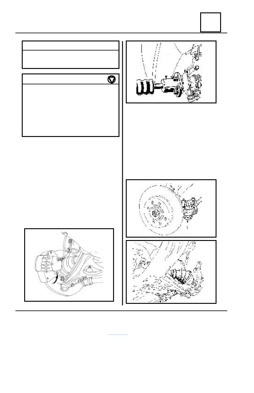
DISMOUNTING

Loosen the front wheel attachment screws.
Lift the vehicle by means of an elevator with

two columns

Dismount :

- the wheel
- the brake disk assembly together with

the flexible connection;.

- the transmission gear nut;
- the brake disk assembly by means of

the PF 600 extractor.

Continue by dismounting the steering

knuckle, observing the operations sequence:

- dismount the steering ball joint nut;
- depress the steering ball joint by

means of the PF 476 extractor;

- dismount the two screws that attach

the steering knuckle on the shock absorber
leg;

- dismount the attachment screw of the

steering ball joint – steering knuckle;

- detach the steering knuckle.

TIGHTENING 

MOMENTS 

(daNm)

Wheel attachment screw

7.5

Steering ball joint nut

4.0

Transmission nut

28.0

Attachment fork screw on steering knuckle 6.5
Screw nut of the steering knuckle
attachment with the shock absorber leg

10.5

Attachment screw nut of the b

all

joint with the steering knuckle

 6.2

Steering  knuckle

PF 476

PF 600

FRONT AXLES ELEMENTS

31

31 - 14

Steering  knuckle

REMOUNTING

REMARK :
Before remounting check the wear of the bearing, that shall be replaced if the grease

is flown.

Position and press the steering knuckle together with the hub – disk assembly, performing the

operations in  the reverse order, after  previously having greased the steering knuckle grooves.

FRONT AXLES ELEMENTS

31

31 - 15

Steering knuckle bearing  (35 x 65 x 35)

DISMOUNTING

Dismount the steering knuckle  (see method

“Dismounting steering knuckle).

Remove the safety ring ( bore ring) from the

interior of the steering knuckle.

Depress the biconical bearing, using a

→  50 mm  outer diameter rod.

Place the steering  rod  using a bushing with

inner diameter  

→ 67 mm.

REMOUNTING

Introduce in the steering knuckle the bearing

support washer

Press the bearing in the steering knuckle, by

means of  a   

→ 63 mm diameter bushing.

Mount the safety ring in the channel of the

steering knuckle bore.

REMARK:
The operation shall be performed so that

bushing is not pressed on the bearing
support washer, in order to perform a correct
mounting and not to damage the bearing.

The steering knuckle-bearing assembly is

to be placed above the hub and after centering
the support washer, press the bearing on the
hub, using a bushing with the inner diameter
of  Ø36 mm and an exterior diameter of Ø
40 mm.

Continue with the mounting of the steering

knuckle assembly on the vehicle (see the
method “Remounting steering knuckle”)

REMARK :
When replacing the bearing, its spacer

is also to be obligatory replaced.

Φ

Φ

Φ

Φ 50

Φ

Φ

Φ

Φ     67

Φ

Φ

Φ

Φ     64

Φ 40

A

Φ

Φ

Φ

Φ     40

Φ

Φ

Φ

Φ     36

FRONT AXLES ELEMENTS

31

31 - 16

CROSS SECTION

Front suspension

6  daNm

2  daNm

10.5  daNm

2.7 daNm

4 daNm

10.5  daNm

7....7.5 daNm

28 daNm

7.5 daNm

5

1.4

6.2


Content   ..  74  75  76  77   ..