Nissan Frontier D40. Manual - part 266


  Index      Nissan     Nissan Frontier D40 (2010 year) - Service and Repair Manual


Search            


Content   ..  264  265  266  267   ..


Nissan Frontier D40. Manual - part 266


ATP SWITCH

DLN-85

< SYMPTOM DIAGNOSIS >

[TRANSFER: TX15B]

C

E

F

G

H

I

J

K

L

M

A

B

DLN

N

O

P

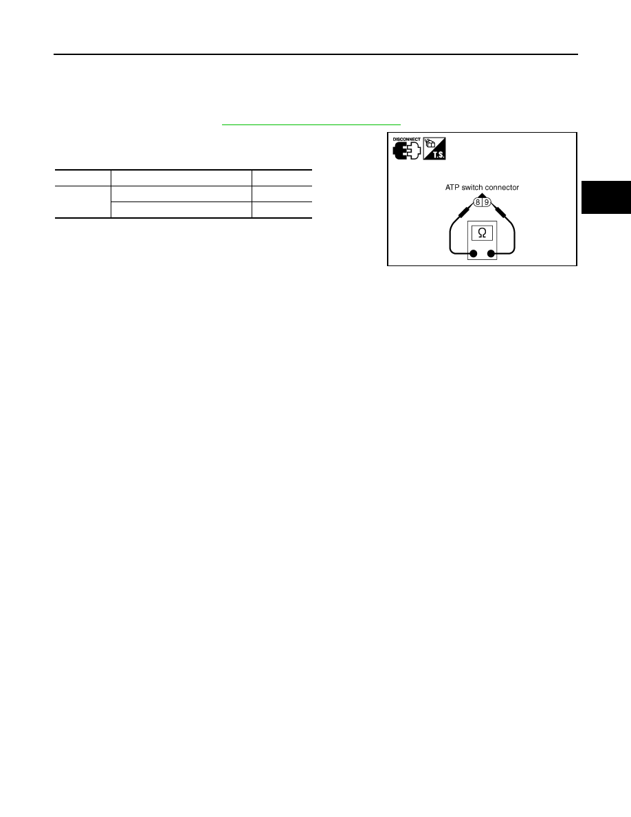
Component Inspection

INFOID:0000000005275476

1.

Turn ignition switch “OFF”.  (Stay for at least 5 seconds.)

2.

Disconnect ATP switch harness connector.

3.

Remove ATP switch.  Refer to 

DLN-13, "Component Parts Location"

.

4.

Push and release ATP switch and check continuity between ATP
switch terminals 8 and 9.

5.

If the inspection results are abnormal replace the ATP switch.

Terminal

Condition

Continuity

8 - 9

Push ATP switch

Yes

Release ATP switch

No

SDIA2395E

DLN-86

< PRECAUTION >

[TRANSFER: TX15B]

PRECAUTIONS

PRECAUTION

PRECAUTIONS

Precaution for Supplemental Restraint System (SRS) "AIR BAG" and "SEAT BELT 
PRE-TENSIONER"

INFOID:0000000005589989

The Supplemental Restraint System such as “AIR BAG” and “SEAT BELT PRE-TENSIONER”, used along
with a front seat belt, helps to reduce the risk or severity of injury to the driver and front passenger for certain
types of collision. This system includes seat belt switch inputs and dual stage front air bag modules. The SRS
system uses the seat belt switches to determine the front air bag deployment, and may only deploy one front
air bag, depending on the severity of a collision and whether the front occupants are belted or unbelted.
Information necessary to service the system safely is included in the SR and SB section of this Service Man-
ual.

WARNING:

• To avoid rendering the SRS inoperative, which could increase the risk of personal injury or death in

the event of a collision which would result in air bag inflation, all maintenance must be performed by
an authorized NISSAN/INFINITI dealer.

• Improper maintenance, including incorrect removal and installation of the SRS, can lead to personal

injury caused by unintentional activation of the system. For removal of Spiral Cable and Air Bag
Module, see the SR section.

• Do not use electrical test equipment on any circuit related to the SRS unless instructed to in this

Service Manual. SRS wiring harnesses can be identified by yellow and/or orange harnesses or har-
ness connectors.

PRECAUTIONS WHEN USING POWER TOOLS (AIR OR ELECTRIC) AND HAMMERS

WARNING:

• When working near the Airbag Diagnosis Sensor Unit or other Airbag System sensors with the Igni-

tion ON or engine running, DO NOT use air or electric power tools or strike near the sensor(s) with a
hammer. Heavy vibration could activate the sensor(s) and deploy the air bag(s), possibly causing
serious injury.

• When using air or electric power tools or hammers, always switch the Ignition OFF, disconnect the

battery, and wait at least 3 minutes before performing any service.

Precaution for Transfer Assembly and Transfer Control Unit Replacement

INFOID:0000000005275478

When replacing transfer assembly or transfer control unit, check the 4WD shift indicator pattern and adjust-
ment of the position between transfer assembly and transfer control unit if necessary.

CHECK 4WD SHIFT INDICATOR PATTERN

1.

Set 4WD shift switch to “2WD”, “4H”, “4LO”, “4H” and “2WD” in order. Stay at each switch position for at
least 2 seconds.

PRECAUTIONS

DLN-87

< PRECAUTION >

[TRANSFER: TX15B]

C

E

F

G

H

I

J

K

L

M

A

B

DLN

N

O

P

2.

Confirm 4WD shift indicator lamp and 4LO indicator lamp change properly as follows.

• If OK, the position between transfer assembly and transfer control unit is correct.
• If NG, the position is different between transfer assembly and transfer control unit.

Adjust the position between transfer assembly and transfer control unit. Refer to pattern table below.

Transfer position adjustment pattern

NOTE:

Method of adjustment can be chosen voluntarily, according to location of 4WD shift switch.

METHOD FOR ADJUSTMENT WITH 4WD SHIFT SWITCH AT “2WD”

Select Adjustment Pattern

1.

Start engine.  Run engine for at least 10 seconds.

2.

Check 4WD shift indicator lamp and 4LO indicator lamp.

Pattern A

1.

Shift the transmission according to the directions below, and stay in "N" for at least 2 seconds.

• For A/T models, stop vehicle and move A/T selector lever to “N” position with brake pedal depressed.
• For M/T models, stop vehicle and move M/T shift lever to the neutral position with brake and clutch pedal

depressed.

2.

Turn 4WD shift switch to “4LO” position.  Stay in "4LO" for at least 2 seconds.

3.

Turn ignition switch “OFF”.

4.

Start engine.

5.

Erase self-diagnosis. Refer to 

DLN-17, "CONSULT-III Function (ALL MODE AWD/4WD)"

.

6.

Check 4WD shift indicator lamp and 4LO indicator lamp again. Refer to "CHECK 4WD SHIFT INDICATOR
PATTERN".
If 4WD shift indicator lamp and 4LO indicator lamp do not indicate proper pattern, install new transfer con-
trol unit and retry the above check.

Pattern B

1.

Shift the transmission according to the directions below, and stay in "N" for at least 2 seconds.

SDIA3289E

4WD shift switch condition

Refer procedure

4WD shift switch is in “2WD” when engine is stopped.

"METHOD FOR ADJUSTMENT WITH 4WD SHIFT 

SWITCH AT “2WD”"

4WD shift switch is in “4H” or “4LO” when engine is stopped.

"METHOD FOR ADJUSTMENT WITH 4WD SHIFT 

SWITCH AT “4H” OR “4LO”"

Indicator lamp condition

Refer procedure

When 4WD shift indicator lamp or 4LO indicator lamp is flashing.

"Pattern A"

Except for above.

"Pattern B"

DLN-88

< PRECAUTION >

[TRANSFER: TX15B]

PRECAUTIONS

• For A/T models, stop vehicle and move A/T selector lever to “N” position with brake pedal depressed.
• For M/T models, stop vehicle and move M/T shift lever to the neutral position with brake and clutch pedal

depressed.

2.

Turn ignition switch “OFF”.

3.

Start engine.

4.

Erase self-diagnosis. Refer to 

DLN-17, "CONSULT-III Function (ALL MODE AWD/4WD)"

.

5.

Check 4WD shift indicator lamp and 4LO indicator lamp again. Refer to "CHECK 4WD SHIFT INDICATOR
PATTERN".
If 4WD shift indicator lamp and 4LO indicator lamp do not indicate proper pattern, install new transfer con-
trol unit and retry the above check.

METHOD FOR ADJUSTMENT WITH 4WD SHIFT SWITCH AT “4H” OR “4LO”

1.

Start engine.  Run the engine for at least 10 seconds.

2.

Shift the transmission according to the directions below, and stay in "N" for at least 2 seconds.

• For A/T models, stop vehicle and move A/T selector lever to “N” position with brake pedal depressed.
• For M/T models, stop vehicle and move M/T shift lever to the neutral position with brake and clutch pedal

depressed.

3.

Turn 4WD shift switch to “2WD” position.  Stay in "2WD" for at least 2 seconds.

4.

Turn ignition switch “OFF”.

5.

Start engine.

6.

Erase self-diagnosis. Refer to 

DLN-17, "CONSULT-III Function (ALL MODE AWD/4WD)"

.

7.

Check 4WD shift indicator lamp and 4LO indicator lamp again. Refer to "CHECK 4WD SHIFT INDICATOR
PATTERN".
If 4WD shift indicator lamp and 4LO indicator lamp do not indicate proper pattern, install new transfer con-
trol unit and retry the above check.

Precaution

INFOID:0000000005275479

• Before connecting or disconnecting the transfer control unit

harness connector, turn ignition switch “OFF” and disconnect
the battery cables. Battery voltage is applied to transfer con-
trol unit even if ignition switch is turned “OFF”.

• When connecting or disconnecting pin connectors into or

from transfer control unit, take care not to damage pin termi-
nals (bend or break).
When connecting pin connectors make sure that there are not
any bends or breaks on transfer control unit pin terminals.

SEF289H

SEF291H


Content   ..  264  265  266  267   ..