Nissan Frontier D40. Manual - part 257
P1818 ACTUATOR POSITION SWITCH
DLN-49
< COMPONENT DIAGNOSIS >
[TRANSFER: TX15B]
C
E
F
G
H
I
J
K
L
M
A
B
DLN
N
O
P
2.
Depress brake pedal and stop vehicle.
3.
Set A/T selector lever to "N" position.
4.
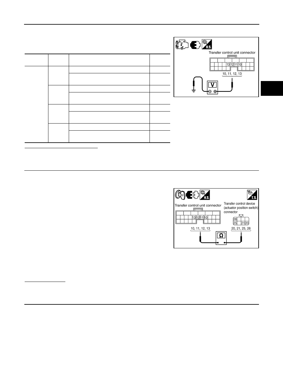
Check voltage between transfer control unit harness connector
terminal and ground.
Are the inspection results normal?
YES
>> GO TO 4.
NO
>> GO TO 2.
2.
CHECK HARNESS BETWEEN TRANSFER CONTROL UNIT AND ACTUATOR POSITION SWITCH
1.
Turn ignition switch “OFF”. (Stay for at least 5 seconds.)
2.
Disconnect transfer control unit harness connector and the transfer control device (actuator position
switch) harness connector.
3.
Check continuity between the following terminals.
-
Transfer control unit harness connector M152 terminal 10 and
transfer control device (actuator position switch) harness con-
nector F58 terminal 26.
-
Transfer control unit harness connector M152 terminal 11 and
transfer control device (actuator position switch) harness con-
nector F58 terminal 20.
-
Transfer control unit harness connector M152 terminal 12 and
transfer control device (actuator position switch) harness con-
nector F58 terminal 21.
-
Transfer control unit harness connector M152 terminal 13 and
transfer control device (actuator position switch) harness con-
nector F58 terminal 25.
Also check harness for short to ground and short to power.
Is there continuity?
YES
>> GO TO 3.
NO
>> Repair or replace damaged parts.
3.
CHECK GROUND CIRCUIT
1.
Turn ignition switch “OFF”. (Stay for at least 5 seconds.)
Connector
Terminal
Condition
Voltage
(Approx.)
M152
10 -
Ground
4WD shift switch: 2WD and 4LO
0V
4WD shift switch: 4H
Battery
voltage
11 -
Ground
4WD shift switch: 4LO
0V
4WD shift switch: 2WD and 4H
Battery
voltage
12 -
Ground
4WD shift switch: 2WD and 4H
0V
4WD shift switch: 4LO
Battery
voltage
13 -
Ground
4WD shift switch: 4H and 4LO
0V
4WD shift switch: 2WD
Battery
voltage
SDIA3369E
Continuity should exist.
SDIA3370E