Nissan Frontier D40. Manual - part 1042


  Index      Nissan     Nissan Frontier D40 (2010 year) - Service and Repair Manual


Search            


Content   ..  1040  1041  1042  1043   ..


Nissan Frontier D40. Manual - part 1042


TM-66

< ON-VEHICLE REPAIR >

[6MT: FS6R31A]

SHIFT CONTROL

SHIFT CONTROL

Removal and Installation

INFOID:0000000005273967
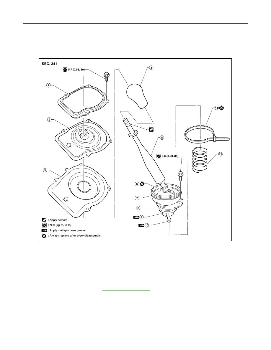
COMPONENTS

REMOVAL

1.

Remove the shift knob.

2.

Remove the M/T finisher. Refer to 

IP-19, "Exploded View"

.

3.

Remove the retaining plate and dust boot covers.

4.

Remove the clip (B) and then separate the boot from the control housing. 

5.

Remove the guide plate bolts and then separate the guide plate. 

6.

Remove the shift lever assembly and spring from the transmission.

INSTALLATION

Installation is the reverse order of removal.
• Install shift knob according to the following.

1.

Retaining plate

2.

Dust boot cover (upper)

3.

Dust boot cover (lower)

4.

Shift knob

5.

Shift lever assembly

6.

Clip (A) 

7.

Boot

8.

Guide plate

9.

Socket

10. Bushing

11.

Clip (B)

12. Spring

WCIA0508E

SHIFT CONTROL

TM-67

< ON-VEHICLE REPAIR >

[6MT: FS6R31A]

C

E

F

G

H

I

J

K

L

M

A

B

TM

N

O

P

- Apply cement to threads of control lever assembly.
- Tighten shift knob until increased tension is felt. Then align shift

knob to the position as shown within one turn.

CAUTION:

Do not adjust shift knob by loosening it.

CAUTION:

• Apply multi-purpose grease to socket and bushing.
• Insert bushing of control lever assembly as far as it will go into the hole of striking arm.
• Tighten guide plate (1) bolts to the specified torque in order as

shown.

• Do not reuse clip.
• Position clip as shown.
• Be careful with the orientation of control lever boot and insu-

lator.

INSPECTION AFTER INSTALLATION

• Tighten guide plate bolts to the specified torque. Refer to 

TM-73, "Overhaul"

.

• When shift lever assembly is shifted to each position, make sure there is no binding or disconnection in

either boot.

• When shifted to each position, make sure there is no noise, bending, and backlash. Especially when shift

lever assembly is shifted to 5th, 6th without pressing downward, check for bending.

• When shift lever assembly is shifted to 1st, 2nd side and 5th, 6th side, confirm shift lever assembly returns to

neutral position smoothly.

• In any position other than reverse, confirm that shift lever assembly can be pressed downward.
• With shift lever assembly pressed downward, confirm that it can be shifted to reverse.
• When shifted from reverse to neutral position, confirm shift lever assembly returns to neutral position

smoothly with spring power.

• Without shift lever assembly pressed downward, confirm that it cannot be shifted to reverse.

PCIB1435E

PCIB1668E

PCIB1434E

TM-68

< ON-VEHICLE REPAIR >

[6MT: FS6R31A]

AIR BREATHER HOSE

AIR BREATHER HOSE

Removal and Installation

INFOID:0000000005273968

Refer to the figure below for air breather hose removal and installation information.

CAUTION:

• Make sure there are no pinched or blocked areas on the air breather hose after installation.
• When inserting the air breather hose, be sure to insert it fully until its end reaches the end of the tube

radius.

• Install the air breather hose with the paint mark side up.

1.

Water outlet

2.

Bracket

3.

Air breather hose

4.

Breather tube

LCIA0392E

TRANSMISSION ASSEMBLY

TM-69

< REMOVAL AND INSTALLATION >

[6MT: FS6R31A]

C

E

F

G

H

I

J

K

L

M

A

B

TM

N

O

P

REMOVAL AND INSTALLATION

TRANSMISSION ASSEMBLY

Removal and Installation from Vehicle (For 2WD Models)

INFOID:0000000005273969

COMPONENTS

REMOVAL

1.

Drain transmission oil. Refer to 

TM-62, "Changing"

.

1.

Transmission assembly

2.

Crossmember

3.

Insulator

AWDIA0687GB


Content   ..  1040  1041  1042  1043   ..