Nissan Altima L32. Manual - part 657


  Index      Nissan     Nissan Altima L32 (2007-2009 year) - Service and Repair Manual


Search            


Content   ..  655  656  657  658   ..


Nissan Altima L32. Manual - part 657


EM-164

< ON-VEHICLE REPAIR >

[VQ35DE]

TIMING CHAIN

12. Place paint marks on the timing chain and sprockets to indicate

the correct position of the components for installation.

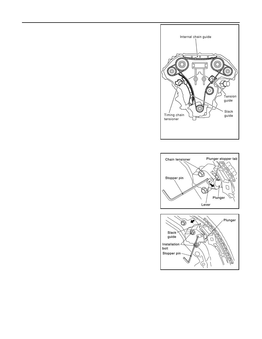
13. Remove the internal chain guide and slack guide. 

14. Remove the timing chain tensioner.
a. Pull lever down and release plunger stopper tab. Plunger stop-

per tab can be pushed up to release (coaxial structure with

lever).

b. Insert stopper pin into tensioner body hole to hold lever, and

keep the tab released. An Allen wrench [1.2 mm (0.047 in)] is

used for a stopper pin as an example.

c.

Insert plunger into tensioner body by pressing the slack side

chain guide.

d. Keep the slack side chain guide pressed and hold it by pushing

the stopper pin through the lever hole and body hole.

e. Remove the bolts and remove the timing chain tensioner.
15. Remove primary timing chain and crankshaft sprocket.

CAUTION:

After removing timing chain, do not turn the crankshaft and

camshaft separately, or the valves will strike the pistons.

SEM740G

SEM732G

SEM733G

TIMING CHAIN

EM-165

< ON-VEHICLE REPAIR >

[VQ35DE]

C

D

E

F

G

H

I

J

K

L

M

A

EM

N

P

O

16. Attach a suitable stopper pin to the right and left camshaft chain

tensioners (for secondary timing chains).

17. Remove the intake and exhaust camshaft sprocket bolts.

• Apply paint to the timing chain and camshaft sprockets for

alignment during installation.

• Secure the hexagonal portion of the camshaft using a wrench

to loosen the bolts.

18. Remove the secondary timing chains with camshaft sprockets.
a. Rotate camshaft slightly, and slacken timing chain of timing

chain tensioner -side.

b. Insert metal or resin plate [0.5 mm (0.020 in)] into guide between

timing chain and chain tensioner plunger. Remove cam sprocket

and secondary timing chain with timing chain removed from

guide groove.

CAUTION:

Chain tensioner plunger can move, while stopper pin is

inserted in tensioner. Plunger can come out of tensioner

when timing chain is removed. Use caution during removal.

• Intake camshaft sprocket is two-for-one structure of primary

and secondary sprockets.

• Handle the intake sprockets as an assembly.

CAUTION:

• Avoid impact or dropping the intake sprockets.

• Do not disassemble the intake sprockets (never loosen

bolts (A) and (B) as shown).

19. Remove the chain tension guide.
20. Remove the rear timing chain case, if necessary. Refer to 

EM-173, "Removal and Installation"

.

SEM923G

WBIA0172E

SEM922G

SEM734G

EM-166

< ON-VEHICLE REPAIR >

[VQ35DE]

TIMING CHAIN

21. Use a scraper to remove all of the old Silicone RTV Sealant from

the front timing chain case and opposite mating surfaces.

CAUTION:

Do not damage the mating surfaces.

22. Remove all old Silicone RTV Sealant from all the bolt holes and

bolts. 

CAUTION:

Do not damage the threads or mating surfaces.

23. Remove the front oil seal from the front timing chain case using

a suitable tool.

CAUTION:

Do not damage the front cover.

Inspection

INFOID:0000000004202169

Check for cracks and any excessive wear of the timing chain. Replace the timing chain as necessary.

Installation

INFOID:0000000004202170

NOTE:

The figure shows the relationship between the mating mark on each timing chain and that on the correspond-

ing sprocket, the components installed.

SEM428G

SEM161F

SEM829E

TIMING CHAIN

EM-167

< ON-VEHICLE REPAIR >

[VQ35DE]

C

D

E

F

G

H

I

J

K

L

M

A

EM

N

P

O

1. Install the rear timing chain case, if removed. Refer to 

EM-173, "Removal and Installation"

.

2. Install the timing chain tension guide.
3. Position the crankshaft so No. 1 piston is set at TDC on the com-

pression stroke.

• Make sure that the dowel pin hole, dowel pin and crankshaft

key are located as shown. 

Camshaft dowel pin hole (intake side): at cylinder head upper

face side in each bank.

Camshaft dowel pin (exhaust side): at cylinder head upper

face side in each bank.

Crankshaft key: at cylinder head side of RH bank.

CAUTION:

Hole on small diameter side must be used for intake camshaft sprocket dowel pin. Do not misiden-

tify (ignore big diameter side).

WBIA0280E

1.

Internal chain guide

2.

Camshaft sprocket (intake)

3.

Mating mark (pink link)

4.

Mating mark (punched)

5.

Secondary timing chain tensioner

6.

Mating mark (orange link)

7.

Secondary timing chain

8.

Camshaft sprocket (exhaust)

9.

Tension guide

10. Water pump

11. Crankshaft sprocket

12. Mating mark (notched)

13. Primary timing chain

14. Slack guide

15. Primary timing chain tensioner

16. Mating mark (back side)

17. Crankshaft key

KBIA1073E


Content   ..  655  656  657  658   ..