Nissan Altima L32. Manual - part 655


  Index      Nissan     Nissan Altima L32 (2007-2009 year) - Service and Repair Manual


Search            


Content   ..  653  654  655  656   ..


Nissan Altima L32. Manual - part 655


EM-156

< ON-VEHICLE REPAIR >

[VQ35DE]

FRONT TIMING CHAIN CASE

1. Remove engine cover using power tool. 
2. Release fuel pressure. Refer to 

EC-1579, "Inspection"

.

3. Remove the air cleaner case, mass air flow sensor and air cleaner to electric throttle control actuator tube.

Refer to 

EM-129, "Removal and Installation"

.

4. Remove the engine coolant reservoir. Refer to 

CO-38, "Removal and Installation"

.

5. Remove the cowl top and cowl top extension. Refer to 

EXT-18, "Removal and Installation"

.

6. Remove the IPDM E/R and position aside. Remove the bracket. Refer to 

PCS-48, "Removal and Installa-

tion"

.

7. Remove the front RH wheel and tire using power tool. Refer to 

WT-66, "Adjustment"

.

8. Remove the engine undercover.
9. Remove the RH inner fender splash shield.
10. Remove the drive belt, idler pulley and drive belt auto-tensioner. Refer to 

EM-121, "Removal and Installa-

tion"

 and 

EM-122, "Removal and Installation of Drive Belt Auto-tensioner"

.

11. Recover the A/C system R134a and remove the A/C compressor. Refer to 

HA-32, "HFC-134a (R-134a)

Service Procedure"

.

12. Remove engine oil cooler pipe bolts.
13. Remove the power steering oil pump and reservoir tank with lines attached and position them aside. Refer

to 

ST-20, "VQ35DE : Removal and Installation"

14. Remove the generator. Refer to 

CHG-27, "Removal and Installation"

.

15. Disconnect the engine harness and position aside.
16. Remove the A/C low-pressure flexible hose. Refer to 

HA-37, "Removal and Installation for Low-Pressure

Flexible Hose"

.

17. Support the engine and remove the RH engine mounting insulator, mount and bracket. Refer to 

EM-202,

"Removal and Installation"

.

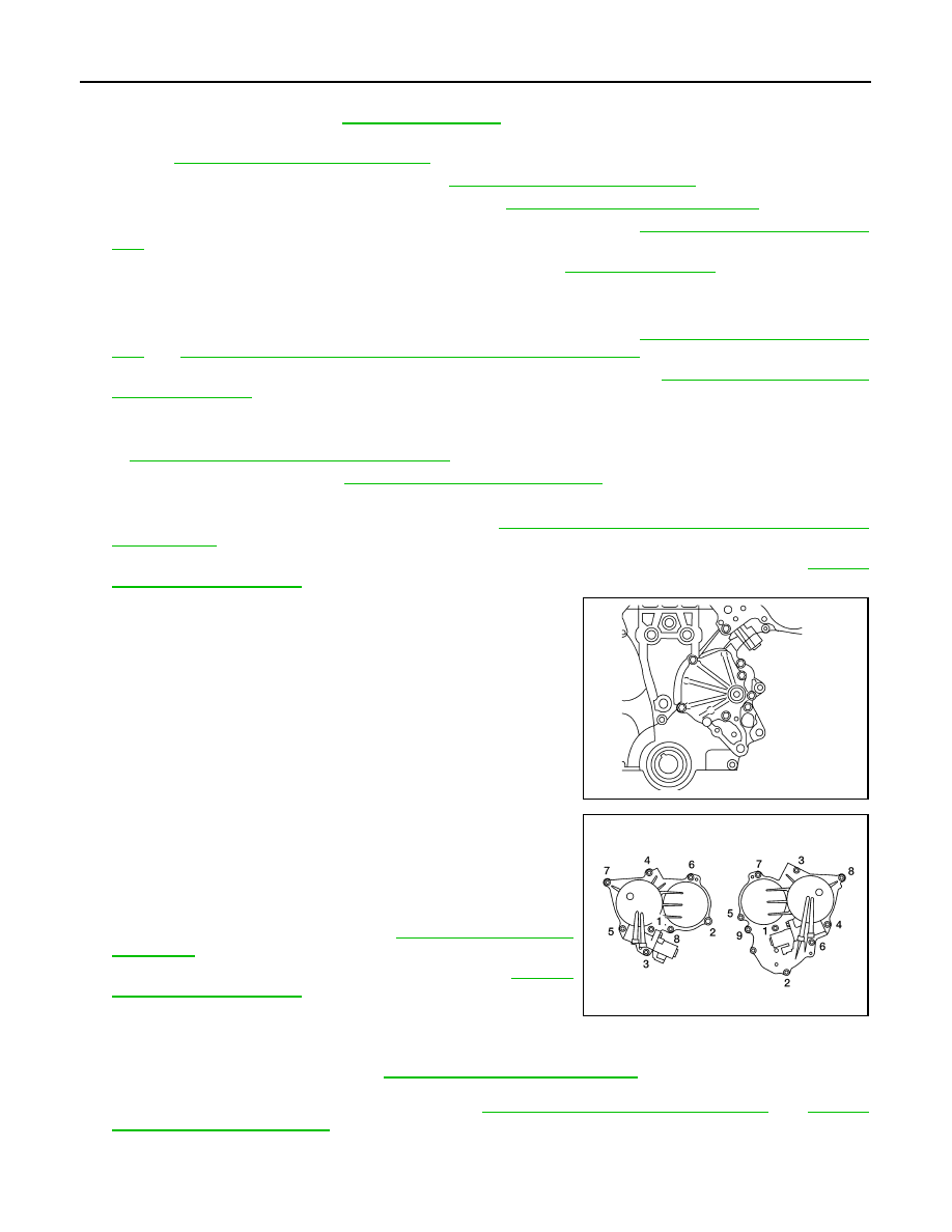
18. Remove the water pump cover, using Tool.

19. Remove the RH and LH IVT covers. Loosen the IVT cover bolts

in the order as shown.

NOTE:

The shaft in the cover is inserted into the center hole of the

intake camshaft sprocket. Remove the cover by pulling straight

out until the cover disengages from the camshaft sprocket.

20. Remove the starter motor. Refer to 

STR-51, "Removal and

Installation"

.

21. Remove the intake manifold collector. Refer to 

EM-133,

"Removal and Installation"

.

22. Remove the six ignition coils.

NOTE:

Note locations for installation.

23. Remove the six spark plugs. Refer to 

EM-119, "Removal and Installation"

.

24. Remove the rocker covers as necessary. Refer to 

EM-151, "Removal and Installation LH"

 and 

EM-152,

"Removal and Installation RH"

.

NOTE:

Necessary only when removing secondary timing chains.

Tool number

: KV10111100 (J-37228)

ALBIA0248ZZ

ALBIA0249ZZ

FRONT TIMING CHAIN CASE

EM-157

< ON-VEHICLE REPAIR >

[VQ35DE]

C

D

E

F

G

H

I

J

K

L

M

A

EM

N

P

O

25. Obtain compression TDC of No. 1 cylinder as follows:
a. Rotate crankshaft pulley clockwise to align timing mark (grooved

line without color) with timing indicator.

b. Check that intake and exhaust camshaft lobes

 on No. 1 cylinder (right bank of engine) are located as shown.

• If not, turn the crankshaft one revolution (360

°) and align as

shown.

26. Lock the drive plate (CVT), flywheel (M/T) using Tool attached to

the starter bolt hole.

CAUTION:

Do not damage the ring gear teeth, or the signal plate teeth

behind the ring gear, when setting the Tool.

27. Remove the crankshaft pulley as follows: 
a. Loosen crankshaft pulley bolt using Tool and locate bolt seating

surface at 10 mm (0.39 in) from its original position.

b. Position a pulley puller at recess hole of crankshaft pulley to

remove crankshaft pulley.

CAUTION:

Do not use a puller claw on crankshaft pulley periphery.

JMBIA1135GB

SEM418G

Tool number

: KV10117700 (J-44716) 

WBIA0580E

Tool number

: KV10109300 

WBIA0386E

EMQ0477D

EM-158

< ON-VEHICLE REPAIR >

[VQ35DE]

FRONT TIMING CHAIN CASE

28. Loosen the lower oil pan bolts using power tool in order as

shown. Remove the lower oil pan. 

a. Insert Tool between the lower oil pan and the upper oil pan.

• Be careful not to damage the mating surface.

• Do not insert a screwdriver, this will damage the mating sur-

faces.

b. Slide (2) the Tool by tapping (1) its side with a hammer to

remove the lower oil pan from the upper oil pan.

29. Remove upper oil pan bolts as shown.

30. Temporarily install lower oil pan.
31. Support front of engine with a suitable jack.
32. Remove the front timing chain case.
a. Loosen the front timing chain case bolts in the order as shown.

WBIA0258E

Tool number

: KV10111100 (J37228)

WBIA0566E

WBIA0259E

ALBIA0250ZZ

FRONT TIMING CHAIN CASE

EM-159

< ON-VEHICLE REPAIR >

[VQ35DE]

C

D

E

F

G

H

I

J

K

L

M

A

EM

N

P

O

b. Insert the appropriate size tool into the notch (A) at the top of the

front timing chain case as shown.

c. Pry off the case by moving the suitable tool (B) as shown.

• Cut liquid gasket for removal using Tool.

CAUTION:

• Do not use a screwdriver or similar tool.

• After removal, handle carefully so it does not bend, or

warp under a load.

33. Remove the front oil seal from the front timing chain case using

a suitable tool.

CAUTION:

Do not damage the front cover.

34. Use a scraper to remove all of the old Silicone RTV Sealant from

the front timing chain case and opposite mating surfaces.

CAUTION:

Do not damage the mating surfaces.

INSTALLATION

1. Install dowel pins (right and left) into front timing chain case up

to a point close to taper in order to shorten protrusion length.

ALBIA0251ZZ

SEM829E

SEM428G

PBIC1101E


Content   ..  653  654  655  656   ..