Nissan Altima L32. Manual - part 649


  Index      Nissan     Nissan Altima L32 (2007-2009 year) - Service and Repair Manual


Search            


Content   ..  647  648  649  650   ..


Nissan Altima L32. Manual - part 649


EM-132

< ON-VEHICLE REPAIR >

[VQ35DE]

INTAKE MANIFOLD COLLECTOR

• EVAP canister purge volume control solenoid valve
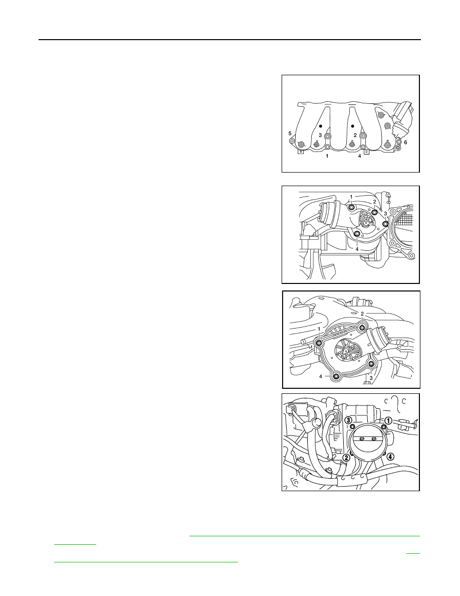
INSTALLATION

Installation is in the reverse order of removal.

• Tighten intake manifold collector bolts in the order as shown.

• Tighten power valve bolts in the order shown.

CAUTION:

The power valve must be held in the closed position during

installation.

• Tighten electric throttle control actuator bolts in the order shown.

NOTE:

After installation, it is necessary to re-calibrate the electric throttle control actuator as follows:

1. Perform the 

″Throttle Valve Closed Position Learning″ when harness connector of the electric throttle con-

trol actuator is disconnected. Refer to 

EC-1053, "THROTTLE VALVE CLOSED POSITION LEARNING :

Description"

.

2. Perform the 

″Idle Air Volume Learning″ when the electric throttle control actuator is replaced. Refer to 

EC-

1053, "IDLE AIR VOLUME LEARNING : Description"

.

ALBIA0240ZZ

ALBIA0229ZZ

ALBIA0230ZZ

SEM711G

INTAKE MANIFOLD

EM-133

< ON-VEHICLE REPAIR >

[VQ35DE]

C

D

E

F

G

H

I

J

K

L

M

A

EM

N

P

O

INTAKE MANIFOLD

Removal and Installation

INFOID:0000000004202160

REMOVAL

WARNING:

To avoid the danger of being scalded, never drain the coolant when the engine is hot.
1. Remove the engine cover with power tool.
2. Release the fuel pressure. Refer to 

EC-1579, "Inspection"

.

3. Remove intake manifold collector. Refer to 

EM-130, "Removal and Installation"

.

4. Disconnect fuel tube quick connector at vehicle piping side.
5. To remove the quick connector cap, hold the sides of the con-

nector, push in the tabs and pull out the tube.

CAUTION:

• The tube can be removed when the tabs are completely

depressed. Do not twist it more than necessary.

• Do not use any tools to remove the quick connector.

• Keep the resin tube away from heat. Be especially careful

when welding near the tube.

• Prevent acid liquids such as battery electrolyte, etc. from

getting on the resin tube.

• Do not bend or twist the tube during removal or installa-

tion.

• Do not remove the remaining retainer on the tube

• When the tube is replaced, also replace the retainer with a new one.

ALBIA0231ZZ

1.

Intake manifold

2.

Gasket

A.

Follow installation procedure

SFE562A

EM-134

< ON-VEHICLE REPAIR >

[VQ35DE]

INTAKE MANIFOLD

• To keep the connecting portion clean and to avoid dam-

age and foreign materials entering, cover the ends of the

fuel tubes with plastic bags or something similar.

NOTE:

If the connector and the tube are stuck together, push and pull

several times until they start to move. Then disconnect them by

pulling.

6. Remove the fuel rail with the fuel injectors attached, from the

intake manifold. Remove the fuel injector O-rings and use new

O-rings for installation.

7. Loosen the bolts in the order as shown, and remove the intake

manifold with power tool.

INSPECTION AFTER REMOVAL

Surface Distortion

• Using straightedge and feeler gauge, inspect the surface distortion

of the intake manifold. Inspect the surface distortion of the intake

manifold collector. Refer to 

EM-130, "Removal and Installation"

.

INSTALLATION

Installation is in the reverse order of removal. Follow the procedure below for specific tightening sequences

and procedures.

• Install intake manifold bolts in two steps in the numerical order as

shown.

NOTE:

After installation, it is necessary to re-calibrate the electric throttle control actuator as follows:

1. Perform the "Throttle Valve Closed Position Learning" when harness connector of the electric throttle con-

trol actuator is disconnected. Refer to 

EC-1053, "THROTTLE VALVE CLOSED POSITION LEARNING :

Special Repair Requirement"

.

2. Perform the "Idle Air Volume Learning" when the electric throttle control actuator is replaced. Refer to 

EC-

1053, "IDLE AIR VOLUME LEARNING : Special Repair Requirement"

.

PBIC0163E

ALBIA0232ZZ

Standard

: 0.1 mm (0.004 in)

WBIA0052E

Step 1

: 7.3 N·m (0.74 kg-m, 65 in-lb)

Step 2

: 25 N·m (2.6 kg-m, 19 ft-lb)

ALBIA0233ZZ

INTAKE MANIFOLD

EM-135

< ON-VEHICLE REPAIR >

[VQ35DE]

C

D

E

F

G

H

I

J

K

L

M

A

EM

N

P

O

• Install the quick connector as follows:

- Make sure no foreign substances are deposited in and around the fuel tube and quick connector and that

there is no damage. 

- Align the center to insert the quick connector straight onto the fuel tube.

- Insert the fuel tube until a click is heard.

- Install the quick connector cap on the quick connector joint. Align

the arrow mark on the quick connector cap to the upper side.

- Install the fuel hose into the hose clamp.

INSPECTION AFTER INSTALLATION

Make sure there is no fuel leakage at connections as follows:
1. Apply fuel pressure to fuel lines by turning ignition switch ON (with engine stopped). Then check for fuel

leaks at connections. 

2. Start the engine and rev it up and check for fuel leaks at connections.

CAUTION:

Do not touch engine immediately after stopping as engine is extremely hot.

NOTE:

Use mirrors for checking on connections out of the direct line of sight.

PBIC0662E


Content   ..  647  648  649  650   ..