Nissan Altima L32. Manual - part 647


  Index      Nissan     Nissan Altima L32 (2007-2009 year) - Service and Repair Manual


Search            


Content   ..  645  646  647  648   ..


Nissan Altima L32. Manual - part 647


EM-124

< ON-VEHICLE MAINTENANCE >

[VQ35DE]

CAMSHAFT VALVE CLEARANCE

CAMSHAFT VALVE CLEARANCE

Valve Clearance

INFOID:0000000004202156

CHECKING

• Perform inspection as follows after removal, installation or replace-

ment of camshaft or valve related parts, or if there is unusual

engine conditions regarding valve clearance.

Check valve clearance while engine is cold and not running.
1. Remove the air duct with air cleaner case, collectors, hoses,

wires, harnesses, and connectors.

2. Remove the intake manifold collectors.
3. Remove the ignition coils and spark plugs.
4. Remove the rocker covers.

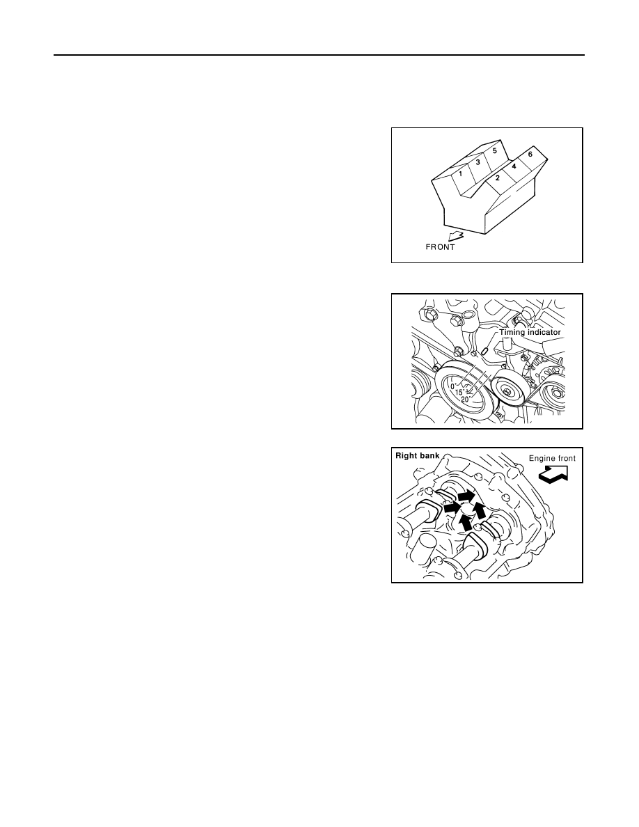
5. Set No.1 cylinder at TDC on its compression stroke.

• Align pointer with TDC mark on crankshaft pulley.

• Check that the valve lifters on No.1 cylinder are loose and

valve lifters on No.4 are tight. If not, turn the crankshaft one full

revolution (360

°) and align as shown.

SEM713A

JMBIA1135GB

SEM418G

CAMSHAFT VALVE CLEARANCE

EM-125

< ON-VEHICLE MAINTENANCE >

[VQ35DE]

C

D

E

F

G

H

I

J

K

L

M

A

EM

N

P

O

6. Check only the valves as shown.

• Using a feeler gauge, measure the clearance between the valve lifter and camshaft.

• Record any valve clearance measurements which are out of specification. They will be used later to

determine the required replacement lifter size.

Valve Clearance for Checking (cold)

7. Turn crankshaft 240

°.

8. Set No.3 cylinder at TDC on its compression stroke.

Crank Position

Valve No. 1

Valve No. 2

Valve No. 3

Valve No. 6

No. 1 TDC

Intake

Exhaust

Exhaust

Intake

SEM893E

Intake

: 0.26 - 0.34 mm (0.010 - 0.013 in)

Exhaust

: 0.29 - 0.37 mm (0.011 - 0.015 in)

SEM139D

KBIA0185E

EM-126

< ON-VEHICLE MAINTENANCE >

[VQ35DE]

CAMSHAFT VALVE CLEARANCE

9. Check only those valves as shown.

10. Turn the crankshaft 240

° and align as above.

11. Set No.5 cylinder at TDC on its compression stroke.
12. Check only those valves as shown.

13. If all valve clearances are within specification, install the following components. If the valve clearances are

out of specification, adjust the valve clearances.

• Intake manifold collectors

• Rocker covers

• All spark plugs

• All ignition coils

VALVE ADJUSTING

Crank Position

Valve No. 2

Valve No. 3

Valve No. 4

Valve No. 5

No. 3 TDC

Intake

Intake

Exhaust

Exhaust

SEM894E

Crank Position

Valve No. 1

Valve No. 4

Valve No. 5

Valve No. 6

No. 5 TDC

Exhaust

Intake

Intake

Exhaust

SEM958E

CAMSHAFT VALVE CLEARANCE

EM-127

< ON-VEHICLE MAINTENANCE >

[VQ35DE]

C

D

E

F

G

H

I

J

K

L

M

A

EM

N

P

O

CAUTION:

Adjust valve clearance while engine is cold.

NOTE:

• Perform adjustment by selecting the correct head thickness of the valve lifter (adjusting shims are not used).

• The specified valve lifter thickness is the dimension at normal temperatures. Ignore dimensional differences

caused by temperature. Use specifications for hot engine condition to confirm valve clearances.

1. Remove the camshaft.
2. Remove the valve lifter that was measured as being outside the standard specifications.
3. Measure the center thickness of the removed lifter with a

micrometer, as shown.

4. Use the equation below to calculate the replacement valve lifter

thickness.

Valve lifter thickness calculation equation: t = t1 + (C1 - C2)

t = thickness of the replacement lifter

t1 = thickness of the removed lifter

C1 = measured valve clearance

C2 = standard valve clearance

• The thickness of the new valve lifter can be identified by the

stamp mark on the reverse side (inside the lifter).

• Available thickness of the valve lifter (factory setting):

7.88 - 8.40 mm (0.3102 - 0.3307 in), in 0.02 mm (0.0008 in)

increments, in 27 sizes (intake / exhaust). Refer to 

EM-231,

"Cylinder Head"

.

5. Install the selected replacement valve lifter.
6. Install the camshaft.
7. Rotate the crankshaft a few turns by hand.
8. Confirm that the valve clearances are within specification.
9. After the engine has been run to full operating temperature, confirm that the valve clearances are within

specification.

* Approximately 80

°C (176°F)

SEM754G

SEM755G

Standard Valve Clearance

Cold

Hot* (reference data)

Intake

0.26 - 0.34 mm (0.010 - 0.013 in)

0.304 - 0.416 mm (0.012 - 0.016 in)

Exhaust

0.29 - 0.37 mm (0.011 - 0.015 in)

0.308 - 0.432 mm (0.012 - 0.017 in)


Content   ..  645  646  647  648   ..