Nissan Altima L32. Manual - part 544


  Index      Nissan     Nissan Altima L32 (2007-2009 year) - Service and Repair Manual


Search            


Content   ..  542  543  544  545   ..


Nissan Altima L32. Manual - part 544


P0340, P0345 CMP SENSOR (PHASE)

EC-1297

< COMPONENT DIAGNOSIS >

[VQ35DE]

C

D

E

F

G

H

I

J

K

L

M

A

EC

N

P

O

1. Start engine and let it idle for at least 5 seconds.

If engine does not start, crank engine for at least 2 seconds.

2. Check 1st trip DTC.
Is 1st trip DTC detected?

YES

>> Go to 

EC-1297, "Diagnosis Procedure"

.

NO

>> GO TO 3.

3.

PERFORM DTC CONFIRMATION PROCEDURE-I

1. Maintaining engine speed at more than 800 rpm for at least 5 seconds.

2. Check 1st trip DTC.
Is 1st trip DTC detected?

YES

>> Go to 

EC-1297, "Diagnosis Procedure"

.

NO

>> INSPECTION END

Diagnosis Procedure

INFOID:0000000004362146

1.

CHECK STARTING SYSTEM

Turn ignition switch to START position.
Does the engine turn over? Does the starter motor operate?

YES

>> GO TO 2.

NO

>> Check starting system. (Refer to 

STR-29, "Work Flow"

.)

2.

CHECK GROUND CONNECTION

1. Turn ignition switch OFF.

2. Check ground connection E9. Refer to Ground Inspection in 

GI-45, "Circuit Inspection"

.

Is the inspection result normal?

YES

>> GO TO 3.

NO

>> Repair or replace ground connection.

3.

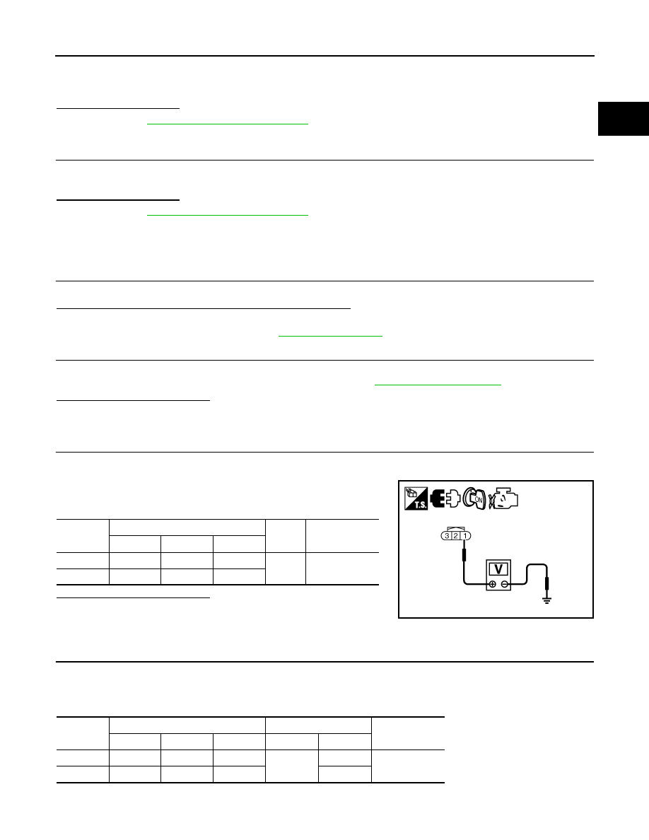
CHECK CAMSHAFT POSITION (CMP) SENSOR (PHASE) POWER SUPPLY CIRCUIT

1. Disconnect camshaft position (CMP) sensor (PHASE) harness connector.

2. Turn ignition switch ON.

3. Check the voltage between CMP sensor (PHASE) harness con-

nector and ground.

Is the inspection result normal?

YES

>> GO TO 4.

NO

>> Repair open circuit or short to ground or short to power

in harness or connectors.

4.

CHECK CMP SENSOR (PHASE) GROUND CIRCUIT FOR OPEN AND SHORT

1. Turn ignition switch OFF.

2. Disconnect ECM harness connector.

3. Check the continuity between CMP sensor (PHASE) harness connector and ECM harness connector.

4. Also check harness for short to ground and short to power.

DTC

CMP sensor (PHASE)

Ground

Voltage (V)

Bank

Connector

Terminal

P0340

1

F55

1

Ground

Approx. 5

P0345

2

F60

1

PBIB3312E

DTC

CMP sensor (PHASE)

ECM

Continuity

Bank

Connector

Terminal

Connector

Terminal

P0340

1

F55

2

F13

64

Existed

P0345

2

F60

2

68

EC-1298

< COMPONENT DIAGNOSIS >

[VQ35DE]

P0340, P0345 CMP SENSOR (PHASE)

Is the inspection result normal?

YES

>> GO TO 5.

NO

>> Repair open circuit, short to ground or short to power in harness or connectors.

5.

CHECK CMP SENSOR (PHASE) INPUT SIGNAL CIRCUIT FOR OPEN AND SHORT

1. Check the continuity between CMP sensor (PHASE) harness connector and ECM harness connector.

2. Also check harness for short to ground and short to power.
Is the inspection result normal?

YES

>> GO TO 6.

NO

>> Repair open circuit, short to ground or short to power in harness or connectors.

6.

CHECK CAMSHAFT POSITION SENSOR (PHASE)

Refer to 

EC-1298, "Component Inspection"

.

Is the inspection result normal?

YES

>> GO TO 7.

NO

>> Replace malfunctioning camshaft position sensor (PHASE).

7.

CHECK CAMSHAFT (INT)

Check the following.

• Accumulation of debris to the signal plate of camshaft rear end

• Chipping signal plate of camshaft rear end
Is the inspection result normal?

YES

>> GO TO 8.

NO

>> Remove debris and clean the signal plate of camshaft

rear end or replace camshaft.

8.

CHECK INTERMITTENT INCIDENT

Refer to 

GI-42, "Intermittent Incident"

.

>> INSPECTION END

Component Inspection

INFOID:0000000004362147

1.

CHECK CAMSHAFT POSITION SENSOR (PHASE)-I

1. Turn ignition switch OFF.

2. Loosen the fixing bolt of the sensor.

3. Disconnect camshaft position sensor (PHASE) harness connector.

4. Remove the sensor.

DTC

CMP sensor (PHASE)

ECM

Continuity

Bank

Connector

Terminal

Connector

Terminal

P0340

1

F55

3

F13

70

Existed

P0345

2

F60

3

69

JMBIA0058ZZ

P0340, P0345 CMP SENSOR (PHASE)

EC-1299

< COMPONENT DIAGNOSIS >

[VQ35DE]

C

D

E

F

G

H

I

J

K

L

M

A

EC

N

P

O

5. Visually check the sensor for chipping.
Is the inspection result normal?

YES

>> GO TO 2.

NO

>> Replace malfunctioning camshaft position sensor

(PHASE).

2.

CHECK CAMSHAFT POSITION SENSOR (PHASE)-II

Check resistance camshaft position sensor (PHASE) terminals as

per the following.

Is the inspection result normal?

YES

>> INSPECTION END

NO

>> Replace malfunctioning camshaft position sensor

(PHASE).

JMBIA0065ZZ

Terminal No. (Polarity)

Resistance

1 (+) - 2 (-)

Except 0 or 

∞ Ω [at 25°C (77°F)]

1 (+) - 3 (-)

2 (+) - 3 (-)

PBIA9584J

EC-1300

< COMPONENT DIAGNOSIS >

[VQ35DE]

P0420, P0430 THREE WAY CATALYST FUNCTION

P0420, P0430 THREE WAY CATALYST FUNCTION

DTC Logic

INFOID:0000000004362148

DTC DETECTION LOGIC

The ECM monitors the switching frequency ratio of air fuel ratio (A/F)

sensor 1 and heated oxygen sensor 2.

A three way catalyst (manifold) with high oxygen storage capacity

will indicate a low switching frequency of heated oxygen sensor 2.

As oxygen storage capacity decreases, the heated oxygen sensor 2

switching frequency will increase.

When the frequency ratio of A/F sensor 1 and heated oxygen sensor

2 approaches a specified limit value, the three way catalyst (mani-

fold) malfunction is diagnosed.

DTC CONFIRMATION PROCEDURE

1.

INSPECTION START

Will CONSULT-III be used?

YES

>> GO TO 2.

NO

>> GO TO 7.

2.

PRECONDITIONING

If DTC Confirmation Procedure has been previously conducted, always perform the following before conduct-

ing the next test.

1. Turn ignition switch OFF and wait at least 10 seconds.

2. Turn ignition switch ON.

3. Turn ignition switch OFF and wait at least 10 seconds.

TESTING CONDITION:

Do not maintain engine speed for more than the specified minutes below.

>> GO TO 3.

3.

PERFORM DTC CONFIRMATION PROCEDURE-I

With CONSULT-III

1. Turn ignition switch ON and select “DATA MONITOR” mode with CONSULT-III.

2. Start engine and warm it up to the normal operating temperature.

3. Turn ignition switch OFF and wait at least 10 seconds.

4. Turn ignition switch ON.

5. Turn ignition switch OFF and wait at least 10 seconds.

6. Start engine and keep the engine speed between 3,500 and 4,000 rpm for at least 1 minute under no load.

7. Let engine idle for 1 minute.

8. Check that “COOLAN TEMP/S” indicates more than 70

°C (158°F).

If not, warm up engine and go to next step when “COOLAN TEMP/S” indication reaches 70

°C (158°F).

9. Open engine hood.

10. Select “DTC & SRT CONFIRMATION” then “SRT WORK SUPPORT” mode with CONSULT-III.

PBIB2055E

DTC No.

Trouble diagnosis name

DTC detecting condition

Possible cause

P0420

Catalyst system efficien-
cy below threshold 
(bank 1)

• Three way catalyst (manifold) does not oper-

ate properly.

• Three way catalyst (manifold) does not have 

enough oxygen storage capacity.

• Three way catalyst (manifold)
• Exhaust tube
• Intake air leakage
• Fuel injector
• Fuel injector leakage
• Spark plug
• Improper ignition timing

P0430

Catalyst system efficien-
cy below threshold 
(bank 2)


Content   ..  542  543  544  545   ..