Nissan Altima L32. Manual - part 186


  Index      Nissan     Nissan Altima L32 (2007-2009 year) - Service and Repair Manual


Search            


Content   ..  184  185  186  187   ..


Nissan Altima L32. Manual - part 186


CHG-28

< ON-VEHICLE REPAIR >

GENERATOR

operation inspection should be performed after replacing the generator, and then make sure that the system

operates normally. Refer to 

CHG-6, "System Description"

.

VQ35DE

REMOVAL

1. Disconnect the battery negative terminal. Refer to 

PG-68, "Removal and Installation"

 (Coupe models) or

PG-139, "Removal and Installation"

 (Sedan models).

2. Partially drain engine coolant. Refer to 

CO-35, "Changing Engine Coolant"

.

3. Remove engine room cover.
4. Remove RH front wheel and tire assembly. Refer to 

WT-66, "Adjustment"

.

5. Remove engine side undercover using power tools.
6. Remove air cleaner and duct assembly. Refer to 

EM-129, "Removal and Installation"

.

7. Remove battery tray. Refer to 

PG-68, "Removal and Installation"

 (Coupe models) or 

PG-139, "Removal

and Installation"

 (Sedan models).

8. Remove cooling fan assembly. Refer to 

CO-40, "Removal and Installation"

.

9. Evacuate A/C system. Refer to 

HA-32, "HFC-134a (R-134a) Service Procedure"

.

10. Remove drive belt. Refer to 

EM-121, "Removal and Installation"

.

11. Remove the A/C compressor. Refer to 

HA-36, "Removal and Installation for Compressor - VQ35DE Mod-

els"

.

12. Remove idler pulley. 
13. Remove A/C idler pulley.
14. Disconnect oil pressure switch.
15. Disconnect the generator harness connectors.
16. Remove the generator bolt and nuts, using power tools.
17. Slide the generator out and remove.
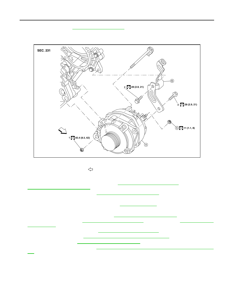
ALMIA0453GB

1.-3. Tightening order

4.

Generator

5.

B terminal nut

6.

Generator bracket

Front

CHG

GENERATOR

CHG-29

< ON-VEHICLE REPAIR >

C

D

E

F

G

H

I

J

K

L

B

A

O

P

N

INSTALLATION

Installation is in the reverse order of removal.

CAUTION:

Be sure to tighten “B” terminal nut carefully.

• Install generator and check tension of belt. Refer to 

EM-121, "Checking Drive Belts"

.

• For this model, the power generation voltage variable control system that controls the power generation volt-

age of the generator has been adopted. Therefore, the power generation voltage variable control system

operation inspection should be performed after replacing the generator, and then make sure that the system

operates normally. Refer to 

CHG-6, "System Description"

.

Inspection

INFOID:0000000004205669

GENERATOR PULLEY INSPECTION

Perform the following.

• Make sure that generator pulley does not rattle.

• Make sure that generator pulley nut is tight.

Generator pulley nut : 118 N·m (12.0 kg-m, 87 ft-lb)

CHG-30

< SERVICE DATA AND SPECIFICATIONS (SDS) 

SERVICE DATA AND SPECIFICATIONS (SDS)

SERVICE DATA AND SPECIFICATIONS (SDS)

SERVICE DATA AND SPECIFICATIONS (SDS)

Generator

INFOID:0000000004205670

Application

QR25DE

VQ35DE

Type

TG12C033

H130-135D1

Valeo

Mitsubishi

Nominal rating

14V-110A

12V-130A

Ground polarity

Negative

Minimum revolution under no-load 

1,200 rpm

1,000 rpm

Hot output current (When 13.5 volts is applied)

More than 47A/1,500 rpm
More than 74A/1,800 rpm

More than 103A/2,500 rpm

More than 117A/5,000 rpm

More than 61A/1,500 rpm

More than 109A/2,500 rpm
More than 129A/5,000 rpm

Regulated output voltage

13.5V @ 5,000 rpm @ 20

°C

13.5V @ 5,000 rpm @ 20

°C

Adjustment range of power generation variable 
voltage control

11.4 - 15.6V

11.4 - 15.6V

CL-1

TRANSMISSION & DRIVELINE

C

E

F

G

H

I

J

K

L

M

SECTION 

CL

A

B

CL

N

O

P

CONTENTS

CLUTCH

SYMPTOM DIAGNOSIS  ...............................

2

NOISE, VIBRATION AND HARSHNESS 
(NVH) TROUBLESHOOTING  .............................

2

NVH Troubleshooting Chart  ......................................

2

PRECAUTION ...............................................

3

PRECAUTIONS ...................................................

3

Precaution for Supplemental Restraint System 
(SRS) "AIR BAG" and "SEAT BELT PRE-TEN-
SIONER" .................................................................
..

3

Precautions Necessary for Steering Wheel Rota-
tion after Battery Disconnect  ...................................
..

3

Precaution for Procedure without Cowl Top Cover 

......

4

Service Notice or Precautions ...................................

4

PREPARATION ............................................

5

PREPARATION ...................................................

5

Special Service Tools ................................................

5

Commercial Service Tools  ........................................

5

ON-VEHICLE MAINTENANCE .....................

6

CLUTCH PEDAL  .................................................

6

Inspection and Adjustment ........................................

6

CLUTCH FLUID ...................................................

7

Air Bleeding Procedure  .............................................

7

ON-VEHICLE REPAIR ..................................

9

CLUTCH PEDAL ................................................

9

Exploded View ..........................................................

9

Removal and Installation  ..........................................

9

Inspection .................................................................

9

CLUTCH MASTER CYLINDER  ........................

10

Removal and Installation  .........................................

10

CLUTCH PIPING ...............................................

12

Exploded View .........................................................

12

Removal and Installation  .........................................

12

REMOVAL AND INSTALLATION ...............

13

CSC (CONCENTRIC SLAVE CYLINDER)  .......

13

Exploded View .........................................................

13

Removal and Installation  .........................................

13

CLUTCH DISC AND CLUTCH COVER  ............

14

Exploded View .........................................................

14

Removal and Installation  .........................................

14

Inspection ................................................................

15

SERVICE DATA AND SPECIFICATIONS 
(SDS) ............................................................

17

SERVICE DATA AND SPECIFICATIONS 
(SDS) .................................................................

17

Clutch Control System .............................................

17

Clutch Pedal  ............................................................

17

Clutch Disc  ..............................................................

17

Clutch Cover ............................................................

17


Content   ..  184  185  186  187   ..