Nissan Altima L32. Manual - part 1518


  Index      Nissan     Nissan Altima L32 (2007-2009 year) - Service and Repair Manual


Search            


Content   ..  1516  1517  1518  1519   ..


Nissan Altima L32. Manual - part 1518


TM-416

< ON-VEHICLE MAINTENANCE >

[CVT: RE0F10A]

CVT FLUID

ON-VEHICLE MAINTENANCE

CVT FLUID

Inspection

INFOID:0000000004201992

CHECKING CVT FLUID

Fluid level should be checked with the fluid warmed up to 50

° to 80°C (122° to 176°F). The fluid level check

procedure is as follows:
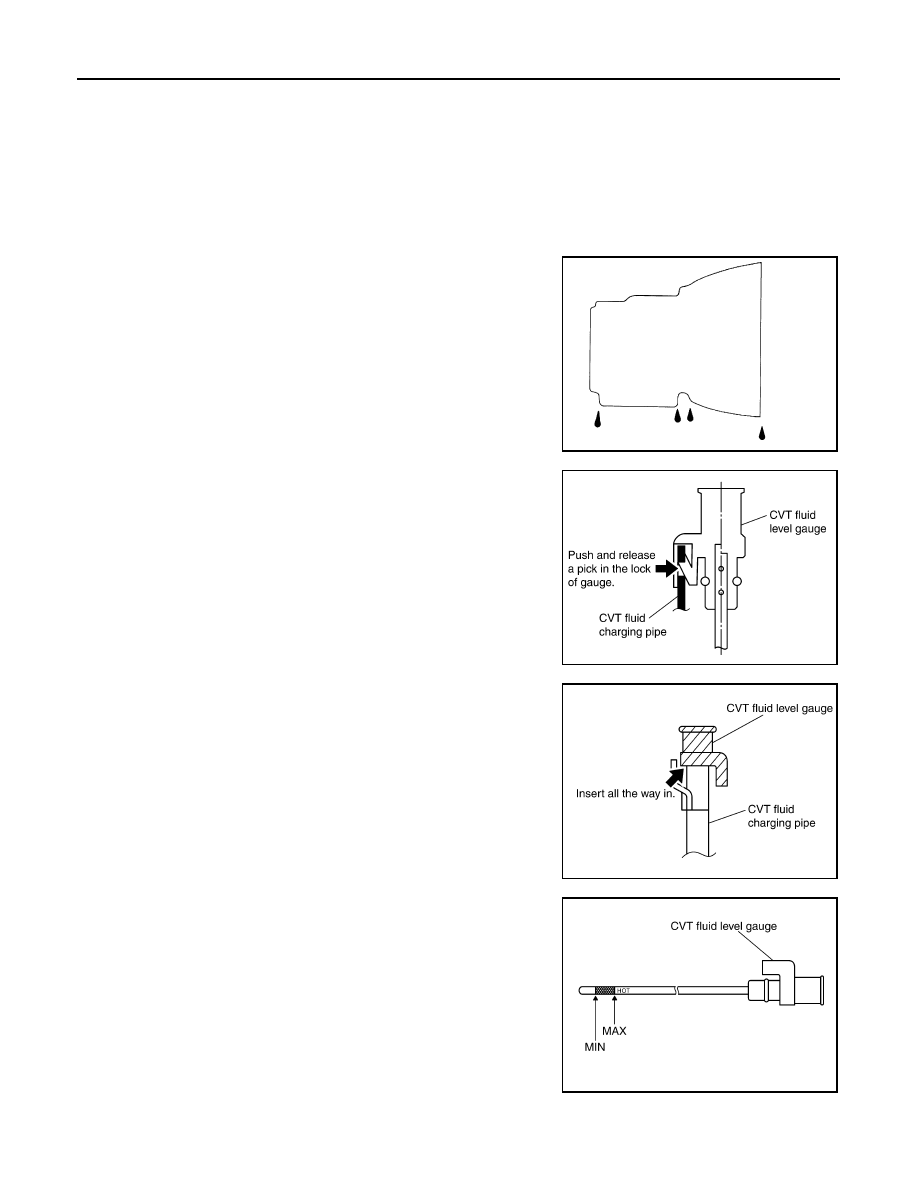
1. Check for fluid leakage.
2. With the engine warmed up, drive the vehicle in an urban area.

When ambient temperature is 20

°C (68°F), it takes about 10

minutes for the CVT fluid to warm up to 50

° to 80°C (122° to

176

°F).

3. Park the vehicle on a level surface.
4. Apply parking brake firmly.
5. With engine at idle, while depressing brake pedal, move shift

selector throughout the entire shift range.

6. Pull out the CVT fluid level gauge from the CVT fluid charging

pipe after pressing the tab on the CVT fluid level gauge to

release the lock.

7. Wipe fluid off the CVT fluid level gauge. Insert the CVT fluid

level gauge rotating 180

° from the originally installed position,

then securely push the CVT fluid level gauge until it meets the

top end of the CVT fluid charging pipe.

CAUTION:

When wiping away the CVT fluid level gauge, always use

lint-free paper, not a cloth rag.

8. Place the selector lever in “P” or “N” and make sure the fluid

level is within the specified range.

CAUTION:

When reinstalling CVT fluid level gauge, insert it into the

CVT fluid charging pipe and rotate it to the original installa-

tion position until it is securely locked.

CVT FLUID CONDITION

SMA146B

SCIA1933E

SCIA1931E

SCIA1932E

CVT FLUID

TM-417

< ON-VEHICLE MAINTENANCE >

[CVT: RE0F10A]

C

E

F

G

H

I

J

K

L

M

A

B

TM

N

O

P

Check CVT fluid condition.

• If CVT fluid is very dark or smells burned, check operation of CVT.

Flush cooling system after repair of CVT.

• If CVT fluid contains frictional material (clutches, brakes, etc.),

replace radiator and flush cooler line using cleaning solvent and

compressed air after repair of CVT. Refer to 

CO-15, "Removal and

Installation"

 and 

TM-418, "Cleaning"

.

Changing CVT Fluid

INFOID:0000000004507223

1. Warm up CVT fluid by driving the vehicle for 10 minutes.

: Vehicle front

• Radiator (2)

• CVT fluid cooler hose [inlet side (3)]

• Transaxle assembly (4)
2. Drain CVT fluid from CVT fluid cooler hose [outlet side (1)] and

refill with new specified NISSAN CVT fluid in the CVT fluid

charging pipe with the engine running at idle speed.

3. Refill until new CVT fluid comes out from CVT fluid cooler hose

[outlet side (1)].

NOTE:

About 30 to 50% extra fluid will be required for this procedure.

4. Check fluid level and condition. Refer to 

TM-416, "Inspection"

.

CAUTION:

• Use only Genuine NISSAN CVT Fluid NS-2. Never mix with other fluid.

• Using CVT fluid other than Genuine NISSAN CVT Fluid NS-2 will deteriorate in driveability and

CVT durability, and may damage the CVT, which is not covered by the warranty.

• When filling CVT fluid, take care not to scatter heat generating parts such as exhaust.

• Sufficiently shake the container of CVT fluid before using.

• Delete CVT fluid deterioration date with CONSULT-III after changing CVT fluid. Refer to TM-34,

"CONSULT-III Function (TRANSMISSION)".

Fluid status

Conceivable cause

Required operation

Varnished (viscous 
varnish state)

CVT fluid become 
degraded due to 
high temperatures.

Replace the CVT fluid and check the 
CVT main unit and the vehicle for 
malfunctions (wire harnesses, cool-
er pipes, etc.)

Milky white or 
cloudy

Water in the fluid

Replace the CVT fluid and check for 
places where water is getting in.

Large amount of 
metal powder mixed 
in

Unusual wear of 
sliding parts within 
CVT

Replace the CVT fluid and check for 
improper operation of the CVT.

ATA0022D

CVT fluid

: Refer to 

TM-451, "General Specification"

Fluid capacity

: Refer to 

TM-451, "General Specification"

SCIA6088E

TM-418

< ON-VEHICLE MAINTENANCE >

[CVT: RE0F10A]

CVT FLUID COOLER SYSTEM

CVT FLUID COOLER SYSTEM

Cleaning

INFOID:0000000004201994

Whenever an automatic transaxle is repaired, overhauled, or replaced, the CVT fluid cooler mounted in the

radiator must be inspected and cleaned.

Metal debris and friction material, if present, can be trapped or become deposit in the CVT fluid cooler. This

debris can contaminate the newly serviced CVT or, in severe cases, can block or restrict the flow of CVT fluid.

In either case, malfunction of the newly serviced CVT may occur.

Debris, if present, may deposit as CVT fluid enters the cooler inlet. It will be necessary to back flush the cooler

through the cooler outlet in order to flush out any built up debris.

CVT FLUID COOLER CLEANING PROCEDURE

1. Position an oil pan under the transaxle's inlet and outlet cooler hoses.
2. Identify the inlet and outlet fluid cooler hoses.
3. Disconnect the fluid cooler inlet and outlet rubber hoses from the

steel cooler tubes or bypass valve.

NOTE:

Replace the cooler hoses if rubber material from the hose

remains on the tube fitting.

4. Allow any CVT fluid that remains in the cooler hoses to drain into

the oil pan.

5. Insert the extension adapter hose of a can of Transmission

Cooler Cleaner (Nissan P/N 999MP-AM006) into the cooler out-

let hose.

CAUTION:

• Wear safety glasses and rubber gloves when spraying the

Transmission Cooler Cleaner.

• Spray Transmission Cooler Cleaner only with adequate

ventilation.

• Avoid contact with eyes and skin.

• Do not breath vapors or spray mist.

6. Hold the hose and can as high as possible and spray Transmis-

sion Cooler Cleaner in a continuous stream into the cooler outlet

hose until CVT fluid flows out of the cooler inlet hose for 5 seconds.

7. Insert the tip of an air gun into the end of the cooler outlet hose.
8. Wrap a shop rag around the air gun tip and end of the cooler

outlet hose.

9. Blow compressed air regulated to 5 to 9 kg/cm

2

 (70 to 130 psi)

through the cooler outlet hose for 10 seconds to force out any

remaining CVT fluid.

10. Repeat steps 5 through 9 three additional times.
11. Position an oil pan under the banjo bolts that connect the CVT

fluid cooler steel lines to the transaxle.

12. Remove the banjo bolts.
13. Flush each steel line from the cooler side back toward the tran-

saxle by spraying Transmission Cooler Cleaner in a continuous stream for 5 seconds.

14. Blow compressed air regulated to 5 to 9 kg/cm

2

 (70 to 130 psi) through each steel line from the cooler

side back toward the transaxle for 10 seconds to force out any remaining CVT fluid.

15. Ensure all debris is removed from the steel cooler lines.
16. Ensure all debris is removed from the banjo bolts and fittings.

SCIA4421E

SCIA4422E

SCIA4423E

CVT FLUID COOLER SYSTEM

TM-419

< ON-VEHICLE MAINTENANCE >

[CVT: RE0F10A]

C

E

F

G

H

I

J

K

L

M

A

B

TM

N

O

P

17. Perform “CVT FLUID COOLER DIAGNOSIS PROCEDURE”.

CVT FLUID COOLER DIAGNOSIS PROCEDURE

NOTE:

Insufficient cleaning of the cooler inlet hose exterior may lead to inaccurate debris identification.
1. Position an oil pan under the transaxle's inlet and outlet cooler hoses.
2. Clean the exterior and tip of the cooler inlet hose.
3. Insert the extension adapter hose of a can of Transmission

Cooler Cleaner (Nissan P/N 999MP-AM006) into the cooler out-

let hose.

CAUTION:

• Wear safety glasses and rubber gloves when spraying the

Transmission Cooler Cleaner.

• Spray Transmission Cooler Cleaner only with adequate

ventilation.

• Avoid contact with eyes and skin.

• Do not breath vapors or spray mist.

4. Hold the hose and can as high as possible and spray Transmis-

sion Cooler Cleaner in a continuous stream into the cooler outlet

hose until CVT fluid flows out of the cooler inlet hose for 5 seconds.

5. Tie a common white, basket-type coffee filter to the end of the

cooler inlet hose.

6. Insert the tip of an air gun into the end of the cooler outlet hose.
7. Wrap a shop rag around the air gun tip and end of cooler outlet

hose.

8. Blow compressed air regulated to 5 to 9 kg/cm

2

 (70 to 130 psi)

through the cooler outlet hose to force any remaining CVT fluid

into the coffee filter.

9. Remove the coffee filter from the end of the cooler inlet hose.
10. Perform “CVT FLUID COOLER INSPECTION PROCEDURE”.

CVT FLUID COOLER INSPECTION PROCEDURE

1. Inspect the coffee filter for debris.
a. If small metal debris less than 1 mm (0.040 in) in size or metal

powder is found in the coffee filter, this is normal. If normal

debris is found, the CVT fluid cooler/radiator can be re-used and

the procedure is ended.

SCIA4421E

SCIA4424E

SCIA4425E

SCIA2967E


Content   ..  1516  1517  1518  1519   ..