Nissan Altima L32. Manual - part 1460


  Index      Nissan     Nissan Altima L32 (2007-2009 year) - Service and Repair Manual


Search            


Content   ..  1458  1459  1460  1461   ..


Nissan Altima L32. Manual - part 1460


TM-184

< COMPONENT DIAGNOSIS >

[CVT: RE0F09B]

P1777 STEP MOTOR

P1777 STEP MOTOR

Description

INFOID:0000000004201762

The step motor changes the step with turning 4 coils ON/OFF according to the signal from TCM. As a result,

the flow of line pressure to primary pulley is changed and pulley ratio is controlled.

DTC Logic

INFOID:0000000004201763

DTC DETECTION LOGIC

DTC CONFIRMATION PROCEDURE

CAUTION:

Always drive vehicle at a safe speed.

NOTE:

If “DTC CONFIRMATION PROCEDURE” has been previously performed, always turn ignition switch OFF.

Then wait at least 10 seconds before performing the next test.

1.

CHECK DTC DETECTION

With CONSULT-III

1. Start engine.

2. Drive vehicle for at least 5 consecutive seconds.

3. Perform “SELF-DIAG RESULTS” mode for “TRANSMISSION”.

With GST

Follow the procedure “With CONSULT-III”.
Is “P1777 STEP MOTR CIRC” detected?

YES

>> Go to 

TM-184, "Diagnosis Procedure"

.

NO

>> Check intermittent incident. Refer to 

GI-42, "Intermittent Incident"

.

Diagnosis Procedure

INFOID:0000000004201764

1.

CHECK STEP MOTOR CIRCUIT

1. Turn ignition switch OFF.

2. Disconnect TCM harness connector.

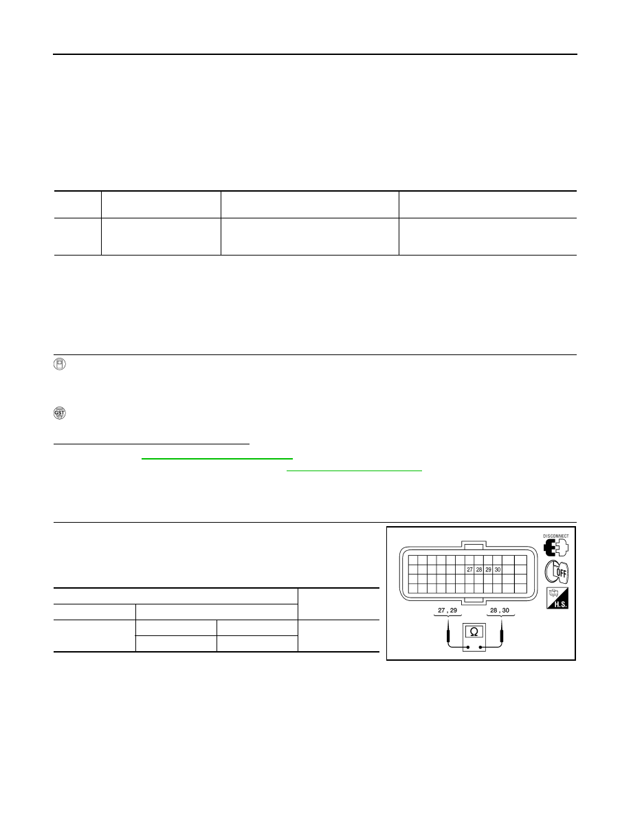
3. Check resistance between TCM harness connector F16 terminal

27, 29 and 28, 30.

DTC

Item

(CONSULT-III screen term)

Malfunction is detected when...

Possible cause

P1777

STEP MOTR CIRC

Each coil of the step motor is not energized 
properly due to an open or a short.

• Harness or connectors

(Step motor circuit is open or shorted.)

• Step motor

TCM harness connector

Resistance (Ap-

prox.)

Connector

Terminal

F16

27

28

30.0 

29

30

AWDIA0148ZZ

P1777 STEP MOTOR

TM-185

< COMPONENT DIAGNOSIS >

[CVT: RE0F09B]

C

E

F

G

H

I

J

K

L

M

A

B

TM

N

O

P

4. Check resistance between TCM harness connector F16 terminal

27, 28, 29, 30 and ground.

Is the inspection result normal?

YES

>> GO TO 5.

NO

>> GO TO 2.

2.

CHECK HARNESS BETWEEN TCM AND CVT UNIT (STEP MOTOR) (PART 1)

1. Disconnect CVT unit harness connector.

2. Check continuity between TCM harness connector F16 (A) ter-

minal 27, 28, 29, 30 and CVT unit harness connector F46 (B)

terminal 9, 8, 7, 6.

Is the inspection result normal?

YES

>> GO TO 3.

NO

>> Repair or replace damaged parts.

3.

CHECK HARNESS BETWEEN TCM AND CVT UNIT (STEP MOTOR) (PART 2)

Check continuity between TCM harness connector F16 terminal 27,

28, 29, 30 and ground.

Is the inspection result normal?

YES

>> GO TO 4.

NO

>> Repair or replace damaged parts.

4.

CHECK STEP MOTOR

Check step motor. Refer to 

TM-186, "Component Inspection (Step Motor)"

.

Is the inspection result normal?

YES

>> GO TO 5.

NO

>> Replace transaxle assembly. Refer to 

TM-259, "Exploded View"

.

5.

DETECT MALFUNCTIONING ITEMS

Check TCM connector pin terminals for damage or loose connection with harness connector.
Is the inspection result normal?

TCM harness connector

Ground

Resistance (Ap-

prox.)

Connector

Terminal

F16

27

15.0 

28

29

30

AWDIA0149ZZ

TCM harness connector

CVT unit harness connector

Continuity

Connector

Terminal

Connector

Terminal

F16 (A)

27

F46 (B)

9

Existed

28

8

29

7

30

6

AWDIA0150ZZ

TCM harness connector

Ground

Continuity

Connector

Terminal

F16

27

Not existed

28

29

30

AWDIA0149ZZ

TM-186

< COMPONENT DIAGNOSIS >

[CVT: RE0F09B]

P1777 STEP MOTOR

YES

>> Replace TCM. Refer to 

TM-254, "Exploded View"

.

NO

>> Repair or replace damaged parts.

Component Inspection (Step Motor)

INFOID:0000000004201765

1.

CHECK STEP MOTOR

1. Check resistance between CVT unit terminal 6, 8 and 7, 9.

2. Check resistance between CVT unit terminal 6, 7, 8, 9 and

ground.

Is the inspection result normal?

YES

>> INSPECTION END

NO

>> Replace transaxle assembly. Refer to 

TM-259, "Exploded View"

.

CVT unit terminals

Resistance (Approx.)

6

7

30.0 

8

9

AWDIA0151ZZ

CVT unit terminal

Ground

Resistance (Approx.)

6

15.0 

7

8

9

AWDIA0152ZZ

P1778 STEP MOTOR - FUNCTION

TM-187

< COMPONENT DIAGNOSIS >

[CVT: RE0F09B]

C

E

F

G

H

I

J

K

L

M

A

B

TM

N

O

P

P1778 STEP MOTOR - FUNCTION

Description

INFOID:0000000004201766

• The step motor's 4 aspects of ON/OFF change according to the signal from TCM. As a result, the flow of line

pressure to primary pulley is changed and pulley ratio is controlled.

• This diagnosis item is detected when electrical system is OK, but mechanical system is NG.

• This diagnosis item is detected when the state of the changing the speed mechanism in unit does not oper-

ate normally.

DTC Logic

INFOID:0000000004201767

DTC DETECTION LOGIC

DTC CONFIRMATION PROCEDURE

CAUTION:

• Always drive vehicle at a safe speed.

• Before starting “DTC CONFIRMATION PROCEDURE”, confirm “Hi” or “Mid” or “Low” fixation by

“PRI SPEED” and “VEHICLE SPEED” on “DATA MONITOR MODE”.

• If hi-geared fixation occurred, go to 

TM-187, "Diagnosis Procedure"

.

NOTE:

If “DTC CONFIRMATION PROCEDURE” has been previously performed, always turn ignition switch OFF.

Then wait at least 10 seconds before performing the next test.

1.

CHECK DTC DETECTION

With CONSULT-III

1. Turn ignition switch ON.

2. Select “DATA MONITOR”.

3. Make sure that output voltage of CVT fluid temperature sensor is within the range below.

4. Start engine and maintain the following conditions for at least 30 consecutive seconds.

With GST

Follow the procedure “With CONSULT-III”.
Is “P1778 STEP MOTR/FNC” detected?

YES

>> Go to 

TM-187, "Diagnosis Procedure"

.

NO

>> Check intermittent incident. Refer to 

GI-42, "Intermittent Incident"

.

Diagnosis Procedure

INFOID:0000000004201768

1.

CHECK STEP MOTOR SYSTEM

Check step motor system. Refer to 

TM-184, "Description"

.

Is the inspection result normal?

DTC

Item

(CONSULT-III screen term)

Malfunction is detected when...

Possible cause

P1778

STEP MOTR/FNC

There is a great difference between the 
number of steps for the stepping motor and 
for the actual gear ratio.

Step motor

ATF TEMP SEN

: 1.0 – 2.0 V

If out of range, drive the vehicle to decrease the voltage (warm up the fluid) or stop engine to increase the voltage (cool 
down the fluid)

TEST START FROM 0 km/h (0 MPH)
CONSTANT ACCELERATION

: Keep 30 sec or more

VEHICLE SPEED

: 10 km/h (6 MPH) or more

ACC PEDAL OPEN

: More than 1.0/8

RANGE

: “D” position

ENG SPEED

: 450 rpm or more


Content   ..  1458  1459  1460  1461   ..