Nissan Altima L32. Manual - part 1071


  Index      Nissan     Nissan Altima L32 (2007-2009 year) - Service and Repair Manual


Search            


Content   ..  1069  1070  1071  1072   ..


Nissan Altima L32. Manual - part 1071


BCM (BODY CONTROL MODULE)

PWC-51

< ECU DIAGNOSIS >

[LH ONLY ANTI-PINCH-COUPE]

C

D

E

F

G

H

I

J

L

M

A

B

PWC

N

O

P

17 

(G/B)

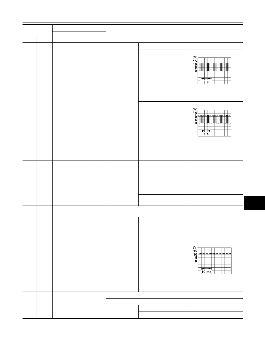
Ground Turn signal (RH)

Output

Ignition switch 
ON

Turn signal switch OFF

0V

Turn signal switch RH

6.5 V

18

(G/Y)

Ground Turn signal (LH)

Output

Ignition switch 
ON

Turn signal switch OFF

0V

Turn signal switch LH

6.5 V

19

(Y)

Ground

Room lamp timer 
control

Output

Interior room 
lamp

OFF

Battery voltage

ON

0V

21

(P/B)

Ground Optical sensor signal

Input

Ignition switch 
ON

When outside of the vehi-
cle is bright

Close to 5V

When outside of the vehi-
cle is dark

Close to 0V

22

(R/Y)

Ground

Clutch interlock 
switch

Input

Clutch interlock 
switch

OFF (clutch pedal is not 
depressed)

0V

ON (clutch pedal is de-
pressed)

Battery voltage

24

(R/W)

Ground Stop lamp switch 1

Input

Battery voltage

26

(O/L)

Ground Stop lamp switch 2

Input

Stop lamp switch

OFF (brake pedal is not de-
pressed)

0V

ON (brake pedal is de-
pressed)

Battery voltage

27

(G/W)

Ground

Front door lock as-
sembly LH (unlock 
sensor)

Input

Front door LH

LOCK status

11.8V

UNLOCK status

0V

29

(Y)

Ground Key slot switch

Input

When Intelligent Key is inserted into key slot

Battery voltage

When Intelligent Key is not inserted into key slot 0V

30

(V/Y)

Ground ACC feedback signal

Input

Ignition switch

OFF

ACC or ON

Battery voltage

Terminal No.

(Wire color)

Description

Condition

Value

(Approx.)

Signal name

Input/ 

Output

(+)

(-)

PKID0926E

PKID0926E

JPMIA0011GB

PWC-52

< ECU DIAGNOSIS >

[LH ONLY ANTI-PINCH-COUPE]

BCM (BODY CONTROL MODULE)

31

(G)

Ground

Rear window defog-
ger feedback signal

Input

Rear window de-
fogger switch

OFF

0V

ON

Battery voltage

32

(R/B)

Ground Front door RH switch

Input

Front door RH 
switch

OFF (when front door RH 
closes)

11.8 V

ON (when front door RH 
opens)

0V

33

(SB)

Ground

Compressor ON sig-
nal

Input

A/C switch

OFF

5V

ON

0V

34

2

(L/R)

Ground

Front door lock as-
sembly LH (key cylin-
der switch) (unlock)

Input

Front door lock 
assembly LH (key 
cylinder switch)

OFF (neutral)

5V

ON (unlock)

0V

36

2

(GR)

Ground Lock switch signal

Input

Door lock/unlock 
switch

Lock

Battery voltage

Unlock

0V

37

(O)

Ground

Trunk lid opener can-
cel switch

Input

Trunk lid opener 
cancel switch

CANCEL

1.1V

ON

0V

38

(GR/

W)

Ground

Rear window defog-
ger ON signal

Input

Rear window de-
fogger switch

OFF

5V

ON

0V

39

2

(GR/

R)

Ground Unlock switch signal

Input

Door lock/unlock 
switch

Unlock

Battery voltage

Lock

0V

40

3

(Y/G)

Ground

Power window serial 
link

Input/

Output

Ignition switch ON

10.2V

Ignition switch OFF or ACC

0V

41

(W)

Ground

Engine switch (push 
switch) illumination

Output

Engine switch 
(push switch) illu-
mination

ON

5.5V

OFF

0V

42

(R)

Ground LOCK indicator lamp

Output

LOCK indicator 
lamp

ON

0V

OFF

Battery voltage

Terminal No.

(Wire color)

Description

Condition

Value

(Approx.)

Signal name

Input/ 

Output

(+)

(-)

JPMIA0011GB

JPMIA0012GB

JPMIA0013GB

BCM (BODY CONTROL MODULE)

PWC-53

< ECU DIAGNOSIS >

[LH ONLY ANTI-PINCH-COUPE]

C

D

E

F

G

H

I

J

L

M

A

B

PWC

N

O

P

45

(P)

Ground

Receiver & sensor 
ground

Input

Ignition switch ON

0V

46

(V/W)

Ground

Receiver & sensor 
power supply output

Output Ignition switch

OFF

0V

ACC or ON

5.0V

47

(G/O)

Ground

Tire pressure receiv-
er signal

Input/

Output

Ignition switch 
ON

Standby state

When receiving the signal 
from the transmitter

48

(R/G)

Ground

Selector lever P/N 
position signal

Input

Selector lever

P or N position

12.0V

Except P and N positions

0V

49

(L/O)

Ground

Security indicator sig-
nal

Output Security indicator

ON

0V

Blinking

11.3V

OFF

Battery voltage

50

(LG/

B)

Ground

Combination switch 
OUTPUT 5

Output

Combination 
switch
(Wiper intermit-
tent dial 4)

All switch OFF

0V

Lighting switch 1ST

10.7V

Lighting switch high-beam

Lighting switch 2ND

Turn signal switch RH

Terminal No.

(Wire color)

Description

Condition

Value

(Approx.)

Signal name

Input/ 

Output

(+)

(-)

OCC3881D

OCC3880D

JPMIA0014GB

JPMIA0031GB

PWC-54

< ECU DIAGNOSIS >

[LH ONLY ANTI-PINCH-COUPE]

BCM (BODY CONTROL MODULE)

51

(L/W)

Ground

Combination switch 
OUTPUT 1

Output

Combination 
switch

All switch OFF
(Wiper intermittent dial 4)

0V

Front wiper switch HI
(Wiper intermittent dial 4)

10.7V

Any of the conditions below 
with all switch OFF
• Wiper intermittent dial 1
• WIper intermittent dial 2
• Wiper intermittent dial 3
• Wiper intermittent dial 6
• Wiper intermittent dial 7

52

(G/B)

Ground

Combination switch 
OUTPUT 2

Output

Combination 
switch

All switch OFF
(Wiper intermittent dial 4)

0V

Front washer switch ON
(Wiper intermittent dial 4)

10.7V

Any of the conditions below 
with all switch OFF
• Wiper intermittent dial 1
• WIper intermittent dial 5
• Wiper intermittent dial 6

53

(LG/

R)

Ground

Combination switch 
OUTPUT 3

Output

Combination 
switch
(Wiper intermit-
tent dial 4)

All switch OFF

0V

Front wiper switch INT

10.7V

Front wiper switch LO

Lighting switch AUTO

54

(G/Y)

Ground

Combination switch 
OUTPUT 4

Output

Combination 
switch
(Wiper intermit-
tent dial 4)

All switch OFF

0V

Front fog lamp switch ON

10.7V

Lighting switch 2ND

Lighting switch flash-to-
pass

Turn signal switch LH

55

(BR/

W)

Ground Front blower monitor

Input

Front blower mo-
tor switch

ON

Battery voltage

OFF

0V

56

2

(L/B)

Ground

Front door lock as-
sembly LH (key cylin-
der switch) (lock)

Input

Front door lock 
assembly LH (key 
cylinder switch)

OFF (neutral)

5V

ON (lock)

0V

57

(W)

Ground

Tire pressure warn-
ing check switch

Input

5V

Terminal No.

(Wire color)

Description

Condition

Value

(Approx.)

Signal name

Input/ 

Output

(+)

(-)

JPMIA0032GB

JPMIA0033GB

JPMIA0034GB

JPMIA0035GB


Content   ..  1069  1070  1071  1072   ..