Nissan Altima L32. Manual - part 84
AV-328
< COMPONENT DIAGNOSIS >
[BOSE AUDIO WITH NAVIGATION]
DOOR SPEAKER (COUPE)
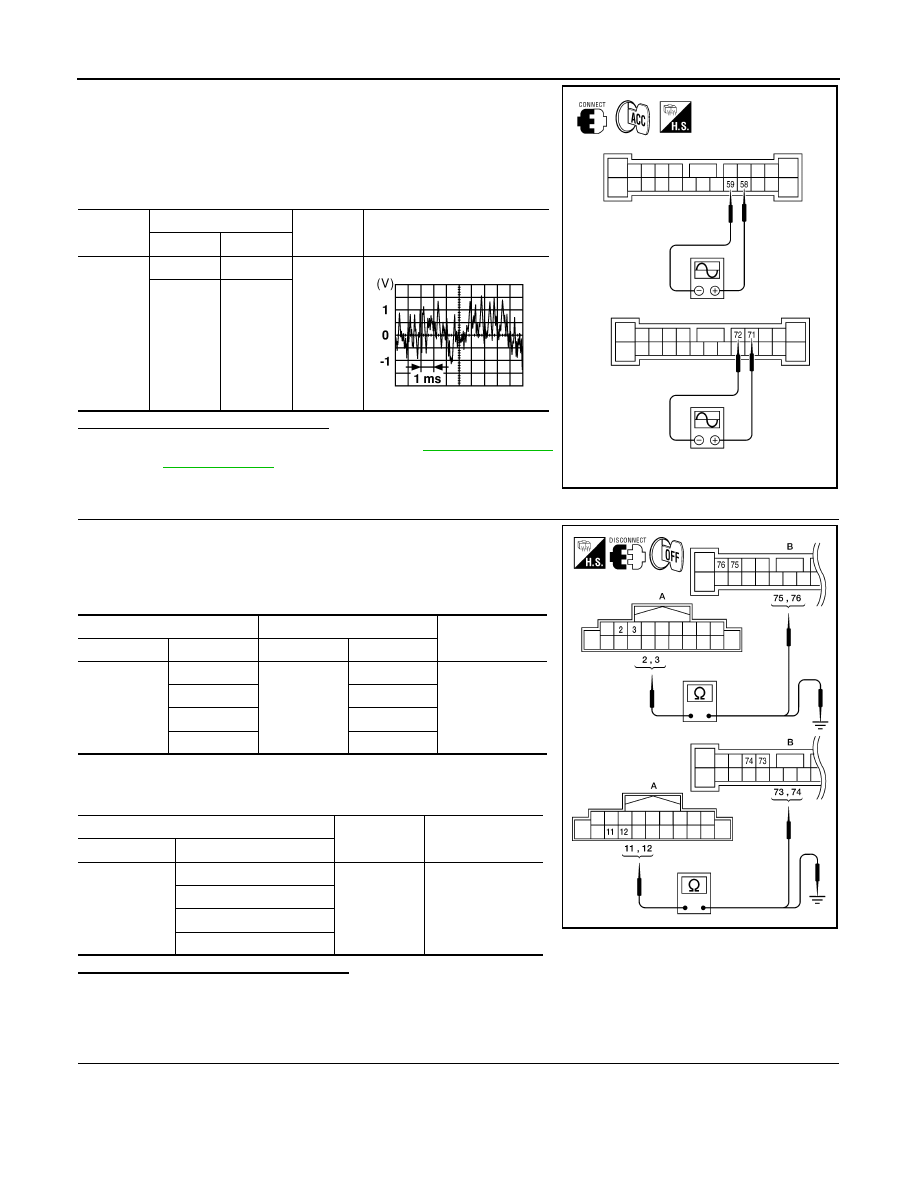
1. Connect BOSE speaker amp. connector B121 and suspect
speaker connector.
2. Turn ignition switch to ACC.
3. Push “POWER” switch.
4. Check the signal between BOSE speaker amp. harness connec-
tor B121 terminals with CONSULT-III or oscilloscope.
Is audio signal voltage as specified?
YES
>> Replace suspect speaker. Refer to
.
NO
>> GO TO 3
3.
HARNESS CHECK
1. Disconnect AV control unit connector M47 and BOSE speaker
amp. connector B121.
2. Check continuity between audio unit harness connector M47 (A)
and BOSE speaker amp. harness connector B121 (B).
3. Check continuity between AV control unit harness connector
M47 (A) and ground.
Are continuity test results as specified?
YES
>> GO TO 4
NO
>> • Check connector housings for disconnected or loose terminals.
• Repair harness or connector.
4.
DOOR SPEAKER SIGNAL CHECK
Connec-
tor
Terminal
Condition
Reference
signal
(+)
(-)
B121
58
59
Receive
audio sig-
nal
71
72
ALNIA0135ZZ
SKIA0177E
A
B
Continuity
Connector
Terminal
Connector
Terminal
M47
2
B121
75
Yes
3
76
11
73
12
74
A
—
Continuity
Connector
Terminal
M47
2
Ground
No
3
11
12
ALNIA0136ZZ