Nissan Terrano model r20 series 2004. Manual - part 190
q
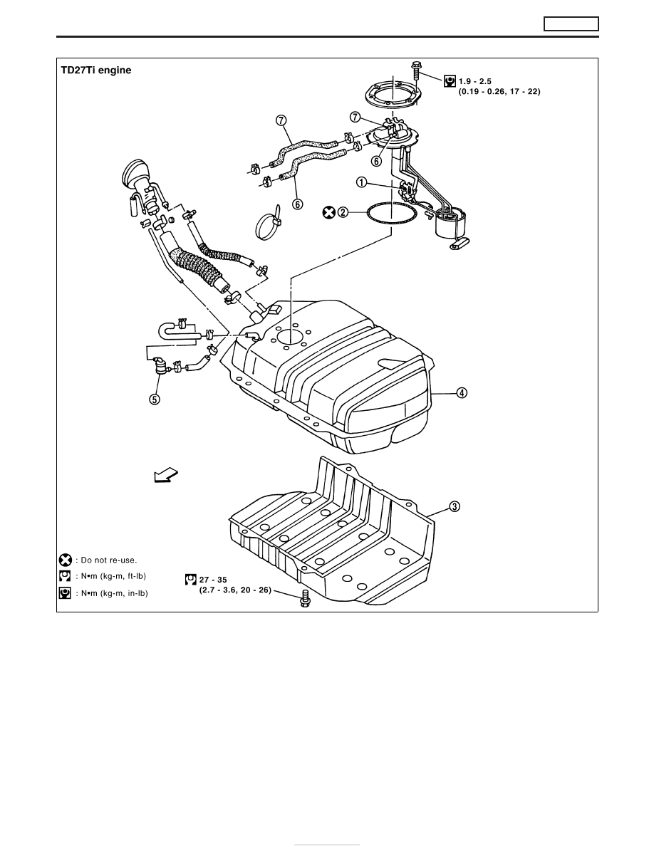
1
Fuel gauge
q
2
O-ring
q
3
Fuel tank protector
q
4
Fuel tank
q
5
Fuel check valve
q
6
Fuel return tube
q
7
Fuel feed tube
YFE071
FUEL SYSTEM
TD27Ti
FE-6
|
|
|
q 1 Fuel gauge q 2 O-ring q 3 Fuel tank protector q 4 Fuel tank q 5 Fuel check valve q 6 Fuel return tube q 7 Fuel feed tube YFE071 FUEL SYSTEM TD27Ti FE-6 |