Nissan Titan A60. Manual - part 712


  Index      Nissan     Nissan Titan A60 (2011 year) - Service and Repair Manual


Search            


Content   ..  710  711  712  713   ..


Nissan Titan A60. Manual - part 712


MA-28

< PERIODIC MAINTENANCE >

ENGINE MAINTENANCE

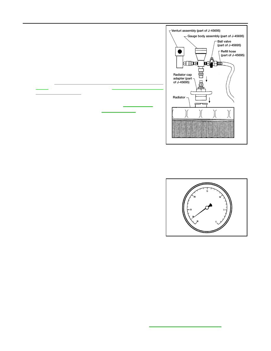
4. Install the Tool by installing the radiator cap adapter onto the

radiator neck opening. Then attach the gauge body assembly

with the refill tube and the venturi assembly to the radiator cap

adapter.

5. Insert the refill hose into the coolant mixture container that is

placed at floor level. Make sure the ball valve is in the closed

position. 

• Use specified coolant or equivalent.

Refer to 

MA-21, "FOR NORTH AMERICA : Fluids and Lubri-

cants"

 (United States and Canada), 

MA-22, "FOR MEXICO :

Fluids and Lubricants"

 (Mexico). 

6. Install an air hose to the venturi assembly, the air pressure must

be within specification. 

CAUTION:

The compressed air supply must be equipped with an air dryer.

7. The vacuum gauge will begin to rise and there will be an audible hissing noise. During this process open

the ball valve on the refill hose slightly. Coolant will be visible rising in the refill hose. Once the refill hose is

full of coolant, close the ball valve. This will purge any air trapped in the refill hose.

8. Continue to draw the vacuum until the gauge reaches 28 inches

of vacuum. The gauge may not reach 28 inches in high altitude

locations, Refer to the following table for expected vacuum read-

ing.

9. When the vacuum gauge has reached the specified amount, disconnect the air hose and wait 20 seconds

to see if the system loses any vacuum. If the vacuum level drops, perform any necessary repairs to the

system and repeat steps 6 - 8 to bring the vacuum to the specified amount. Recheck for any leaks. 

10. Place the coolant container (with the refill hose inserted) at the same level as the top of the radiator. Then

open the ball valve on the refill hose so the coolant will be drawn up to fill the cooling system. The cooling

system is full when the vacuum gauge reads zero.

CAUTION:

Do not allow the coolant container to get too low when filling, to avoid air from being drawn into

the cooling system. 

11. Remove the Tool from the radiator neck opening and install the radiator cap.
12. Remove the non-vented reservoir cap.
13. Fill the cooling system reservoir tank to the specified level. Run the engine to warm up the cooling system

and top up the system as necessary before installing the vented reservoir cap.

FLUSHING COOLING SYSTEM

1. Drain the water from the engine cooling system. Refer to 

MA-26, "Changing Engine Coolant"

.

Tool number

: KV991J0070 (J-45695)

Cooling system capacity 
(with reservoir)

: Refer to 

CO-25, "Stan-

dard and Limit"

.

Compressed air 
supply pressure

: 549 - 824 kPa (5.6 - 8.4 kg/cm

2

80 - 119 psi)

LLIA0058E

Altitude above sea level

Vacuum gauge reading

0 - 100 m (328 ft)

: 28 inches of vacuum

300 m (984 ft)

: 27 inches of vacuum

500 m (1,641 ft)

: 26 inches of vacuum

1,000 m (3,281 ft)

: 24 - 25 inches of vacuum

LLIA0057E

ENGINE MAINTENANCE

MA-29

< PERIODIC MAINTENANCE >

C

D

E

F

G

H

I

J

K

L

M

B

MA

N

O

A

2. Fill the radiator and the reservoir tank (to the “MAX” line), with water. Reinstall the radiator cap and leave

the vented reservoir cap off.

3. Run the engine until it reaches normal operating temperature.
4. Press the engine accelerator two or three times under no-load.
5. Stop the engine and wait until it cools down.
6. Drain the water from the engine cooling system. Refer to 

MA-26, "Changing Engine Coolant"

.

7. Repeat steps 2 through 6 until clear water begins to drain from the radiator.

Checking Fuel Line

INFOID:0000000006158424

Inspect fuel lines, fuel filler cap and fuel tank for improper attach-

ment, leaks, cracks, damage, loose connections, chafing or deterio-

ration.

If necessary, repair or replace damaged parts.

Changing Fuel Filter

INFOID:0000000006158425

The fuel filter is part of the fuel level sensor unit, fuel filter and fuel pump assembly. Refer to 

FL-11

 .

WARNING:

Before replacing the fuel filter, release the fuel pressure from the fuel system. Refer to 

EC-473, "Fuel

Pressure Check"

.

Changing Engine Air Cleaner Filter

INFOID:0000000006158426

REMOVAL

NOTE:

• The viscous paper type filter does not need cleaning between replacement intervals.

• Replace the air filter as necessary for periodic maintenance. Refer to 

MA-9, "FOR NORTH AMERICA : Intro-

duction of Periodic Maintenance"

. (United States and Canada), 

MA-13, "FOR MEXICO : Introduction of Peri-

odic Maintenance"

 (Mexico).

SMA803A

1.

Air cleaner case (lower)

2.

Air cleaner filter

3.

Air cleaner case (upper)

4.

Air duct and resonator assembly

Front

ALBIA0413GB

MA-30

< PERIODIC MAINTENANCE >

ENGINE MAINTENANCE

1. Remove the air duct and resonator assembly.
2. Remove the air cleaner case (upper).
3. Remove the air cleaner filter from the air cleaner case (lower).

INSTALLATION

1. Install the new air cleaner filter in the air cleaner case (lower).
2. Install the air cleaner case (upper).

Changing Engine Oil

INFOID:0000000006158427

WARNING:

• Be careful not to burn yourself, as the engine oil is hot.

• Prolonged and repeated contact with used engine oil may

cause skin cancer. Try to avoid direct skin contact with used

engine oil. If skin contact is made, wash thoroughly with soap

or hand cleaner as soon as possible. 

1. Remove engine under cover or skid plate. Refer to 

EXT-15,

"Removal and Installation"

.

2. Warm up engine, and check for oil leakage from engine compo-

nents. Refer to 

LU-8, "Inspection"

.

3. Stop engine and wait for 10 minutes.
4. Loosen oil filler cap, then remove drain plug.
5. Drain engine oil.
6. Install drain plug with new washer. 

CAUTION:

• Be sure to clean drain plug and install with new washer.

7. Refill with new engine oil. Refer to 

MA-21, "FOR NORTH AMERICA : Fluids and Lubricants"

 (United

States and Canada), 

MA-22, "FOR MEXICO : Fluids and Lubricants"

 (Mexico).

CAUTION:

• The refill capacity depends on the engine oil temperature and drain time. Use these specifica-

tions for reference only.

• Always use the oil level gauge to determine when the proper amount of engine oil is in the

engine.

8. Warm up engine and check area around drain plug and oil filter for oil leakage.
9. Stop engine and wait for 10 minutes.
10. Check engine oil level. Refer to 

LU-8, "Inspection"

.

Changing Oil Filter

INFOID:0000000006158428

REMOVAL

1. Drain the engine oil. Refer to 

LU-9, "Changing Engine Oil"

.

2. Remove the oil filter using Tool.

WARNING:

• Be careful not to get burned when the engine and engine

oil are hot.

CAUTION:

• The oil filter is provided with a relief valve.

Use Genuine NISSAN oil filter or equivalent.

• Be careful not to get burned when the engine and engine

oil are hot.

• When removing, prepare a shop cloth to absorb any engine oil leakage or spillage.

• Do not allow engine oil to adhere to the drive belts.

Oil pan drain plug

: 34.3 N·m (3.5 kg-m, 25 ft-lb)

KBIA2498E

Tool number

: KV10115801 (J-38956)

WBIA0388E

ENGINE MAINTENANCE

MA-31

< PERIODIC MAINTENANCE >

C

D

E

F

G

H

I

J

K

L

M

B

MA

N

O

A

• Completely wipe off any engine oil that adheres to the engine and the vehicle.

INSTALLATION

1. Remove foreign materials adhering to the oil filter installation surface.
2. Apply engine oil to the oil seal circumference of the new oil filter.

3. Screw the oil filter manually until it touches the installation sur-

face, then tighten it by 2/3 turn. Or tighten to specification.

4. Refill the engine with new engine oil. Refer to 

LU-9, "Changing

Engine Oil"

.

5. Install the engine undercover.

6. Inspect the engine for oil leakage. Follow the "INSPECTION AFTER INSTALLATION" procedure.

INSPECTION AFTER INSTALLATION

1. Check the engine oil level. Refer to 

LU-8, "Inspection"

.

2. Start the engine and check for engine oil leakage.
3. Stop the engine and wait for 10 minutes.
4. Check the engine oil level and add engine oil as required.

Changing Spark Plugs

INFOID:0000000006158429

SMA010

Oil filter

: 17.7 N·m (1.8 kg-m, 13 ft-lb)

SMA229B

1.

Ignition coil

2.

Spark plug

WBIA0796E


Content   ..  710  711  712  713   ..