Nissan Titan A60. Manual - part 495
POWER SUPPLY AND GROUND CIRCUIT
EXL-35
< DTC/CIRCUIT DIAGNOSIS >
C
D
E
F
G
H
I
J
K
M
A
B
EXL
N
O
P
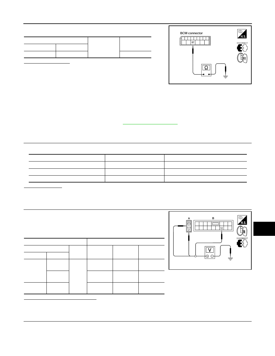
Check continuity between BCM harness connector and ground.
Does continuity exist?
YES
>> Inspection End.
NO
>> Repair or replace harness.
IPDM E/R (INTELLIGENT POWER DISTRIBUTION MODULE ENGINE ROOM)
IPDM E/R (INTELLIGENT POWER DISTRIBUTION MODULE ENGINE ROOM) : Di-
agnosis Procedure
INFOID:0000000006607775
Regarding Wiring Diagram information, refer to
.
1.
CHECK FUSES AND FUSIBLE LINK
Check that the following IPDM E/R fuses or fusible link are not blown.
Is the fuse blown?
YES
>> Replace the blown fuse or fusible link after repairing the affected circuit.
NO
>> GO TO 2
2.
CHECK BATTERY POWER SUPPLY CIRCUIT
1. Turn ignition switch OFF.
2. Disconnect IPDM E/R.
3. Check voltage between IPDM E/R harness connectors and
ground.
Is the measurement value normal?
YES
>> GO TO 3
NO
>> Repair or replace harness.
3.
CHECK GROUND CIRCUIT
1. Turn ignition switch OFF.
BCM
Ground
Continuity
Connector
Terminal
M20
67
Yes
LIIA0915E
Terminal No.
Signal name
Fuses and fusible link No.
1
Battery
A (140A), D (80A)
2
Battery
C (80A)
12
Ignition switch ON or START
59 (10A)
Terminals
Ignition switch position
(+)
(
−)
OFF
ON
START
Connector
Terminal
E118 (A)
1
Ground
Battery
voltage
Battery
voltage
Battery
voltage
2
Battery
voltage
Battery
voltage
Battery
voltage
E119 (B)
12
0V
Battery
voltage
Battery
voltage
AWMIA0023ZZ