Nissan Titan A60. Manual - part 494


  Index      Nissan     Nissan Titan A60 (2011 year) - Service and Repair Manual


Search            


Content   ..  492  493  494  495   ..


Nissan Titan A60. Manual - part 494


DIAGNOSIS SYSTEM (IPDM E/R)

EXL-31

< SYSTEM DESCRIPTION >

C

D

E

F

G

H

I

J

K

M

A

B

EXL

N

O

P

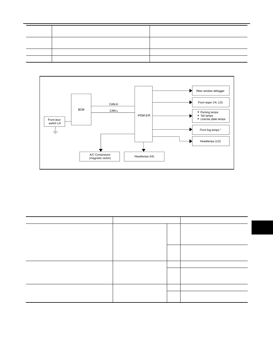
Concept of auto active test

• IPDM E/R starts the auto active test with the door switch signals transmitted by BCM via CAN communica-

tion. Therefore, the CAN communication line between IPDM E/R and BCM is considered normal if the auto

active test starts successfully.

• The auto active test facilitates troubleshooting if any systems controlled by IPDM E/R cannot be operated.

Diagnosis chart in auto active test mode

3

Tail, license, parking lamps and front fog lamps (if 
equipped)

10 seconds

4

Headlamps

LO for 10 seconds 

→ HI on-off for 5 seconds

5

A/C compressor (magnetic clutch)

ON 

⇔ OFF 5 times

Operation 
sequence

Inspection Location

Operation

*: If equipped

AWMIA1108GB

Symptom

Inspection contents

Possible cause

Oil pressure low/coolant temperature high warning 
indicator does not operate

Perform auto active test.
Does the oil pressure low/
coolant temperature high 
warning indicator operate?

YES

• IPDM E/R signal input circuit
• ECM signal input circuit
• CAN communication signal be-

tween ECM and combination meter

NO

CAN communication signal between 
IPDM E/R, BCM and combination 
meter

Oil pressure gauge does not operate

Perform auto active test.
Does the oil pressure gauge 
operate?

YES

IPDM E/R signal input circuit

NO

CAN communication signal between 
IPDM E/R, BCM and combination 
meter

Rear window defogger does not operate

Perform auto active test.
Does the rear window defog-
ger operate?

YES

BCM signal input circuit

NO

CAN communication signal between 
BCM and IPDM E/R

EXL-32

< SYSTEM DESCRIPTION >

DIAGNOSIS SYSTEM (IPDM E/R)

CONSULT - III Function (IPDM E/R)

INFOID:0000000006607774

APPLICATION ITEM

CONSULT-III performs the following functions via CAN communication with IPDM E/R.

SELF DIAGNOSTIC RESULT

Refer to 

PCS-22, "DTC Index"

.

DATA MONITOR

Any of the following components do not operate
• Front wipers
• Tail lamps
• License plate lamps
• Parking  lamps
• Front fog lamps
• Headlamps (HI, LO)

Perform auto active test.
Does the applicable system 
operate?

YES

BCM signal input system

NO

• Lamp or front wiper motor malfunc-

tion

• Lamp or front wiper motor ground 

circuit

• Harness or connector between 

IPDM E/R and applicable system

• IPDM E/R (integrated relay malfunc-

tion)

A/C compressor does not operate

Perform auto active test.
Does the A/C compressor op-
erate?

YES

• BCM signal input circuit
• CAN communication signal be-

tween BCM and ECM

• CAN communication signal be-

tween ECM and IPDM E/R

NO

• Magnetic clutch malfunction
• Harness or connector between 

IPDM E/R and magnetic clutch

• IPDM E/R (integrated relay malfunc-

tion)

Symptom

Inspection contents

Possible cause

Direct Diagnostic Mode

Description

Self Diagnostic Result

The IPDM E/R self diagnostic results are displayed.

Data Monitor

The IPDM E/R input/output data is displayed in real time.

Active Test

The IPDM E/R activates outputs to test components.

CAN Diag Support Mntr

The result of transmit/receive diagnosis of CAN communication is displayed.

Monitor Item [Unit]

Main

Signals

Description

AC COMP REQ [On/Off]

×

Indicates A/C compressor request signal received from ECM on CAN commu-
nication line

TAIL&CLR REQ [On/Off]

×

Indicates position light request signal received from BCM on CAN communica-
tion line

HL LO REQ [On/Off]

×

Indicates low beam request signal received from BCM on CAN communication 
line

HL HI REQ [On/Off]

×

Indicates high beam request signal received from BCM on CAN communication 
line

FR FOG REQ [On/Off]

×

Indicates front fog light request signal received from BCM on CAN communica-
tion line

FR WIP REQ [Stop/1LOW/Low/Hi]

×

Indicates front wiper request signal received from BCM on CAN communication 
line

WIP AUTO STOP [STOP P/ACT P]

×

Indicates condition of front wiper auto stop signal

WIP PROT [Off/BLOCK]

×

Indicates condition of front wiper fail-safe operation

ST RLY REQ [On/Off]

Indicates starter request signal received from ECM on CAN communication line

IGN RLY [On/Off]

×

Indicates condition of ignition relay

DIAGNOSIS SYSTEM (IPDM E/R)

EXL-33

< SYSTEM DESCRIPTION >

C

D

E

F

G

H

I

J

K

M

A

B

EXL

N

O

P

ACTIVE TEST

RR DEF REQ [On/Off]

×

Indicates rear defogger request signal received from AV control unit on CAN 
communication line

OIL P SW [Open/Close]

Indicates condition of oil pressure switch

DTRL REQ [Off]

Indicates daytime light request signal received from BCM on CAN communica-
tion line

THFT HRN REQ [On/Off]

Indicates theft warning horn request signal received from BCM on CAN commu-
nication line

HORN CHIRP [On/Off]

Indicates horn reminder signal received from BCM on CAN communication line

Monitor Item [Unit]

Main

Signals

Description

Test item

Description

REAR DEFOGGER

This test is able to check rear defogger operation [On/Off].

FRONT WIPER

This test is able to check wiper motor operation [Hi/Lo/Off].

MOTOR FAN

This test is able to check cooling fan operation [4/3/2/1].

EXTERNAL LAMPS

This test is able to check external lamp operation [Fog/Hi/Lo/TAIL/Off].

HORN

This test is able to check horn operation [On].

EXL-34

< DTC/CIRCUIT DIAGNOSIS >

POWER SUPPLY AND GROUND CIRCUIT

DTC/CIRCUIT DIAGNOSIS

POWER SUPPLY AND GROUND CIRCUIT

BCM (BODY CONTROL MODULE)
BCM (BODY CONTROL MODULE) : Diagnosis Procedure

INFOID:0000000006607776

Regarding Wiring Diagram information, refer to 

BCS-46, "Wiring Diagram"

.

1.

 CHECK FUSES AND FUSIBLE LINK

Check that the following fuses and fusible link are not blown.

Is the fuse blown?

YES

>> Replace the blown fuse or fusible link after repairing the affected circuit.

NO

>> GO TO 2

2.

 CHECK POWER SUPPLY CIRCUIT

1. Turn ignition switch OFF.

2. Disconnect BCM.

3. Check voltage between BCM harness connector and ground.

Is the measurement value normal?

YES

>> GO TO 3

NO

>> Repair or replace harness.

3.

 CHECK GROUND CIRCUIT

Terminal No.

Signal name

Fuses and fusible link No.

57

Battery power supply

22 (15A)

70

F (50A)

11

Ignition ACC or ON

4 (10A)

38

Ignition ON or START

59 (10A)

Connector

Terminals 

Power

source

Condition

Voltage (V) (Ap-

prox.)

(+)

(-)

M18

11

Ground

ACC 

power 

supply

Ignition 

switch 

ACC or 

ON

Battery voltage

38

Ground

Ignition 

power 

supply

Ignition 

switch ON 

or START

Battery voltage

M20

57

Ground

Battery 

power 

supply

Ignition 

switch 

OFF

Battery voltage

70

Ground

Battery 

power 

supply

Ignition 

switch 

OFF

Battery voltage

LIIA2415E


Content   ..  492  493  494  495   ..