Nissan Titan A60. Manual - part 489
DAYTIME RUNNING LIGHT SYSTEM
EXL-11
< SYSTEM DESCRIPTION >
C
D
E
F
G
H
I
J
K
M
A
B
EXL
N
O
P
DAYTIME RUNNING LIGHT SYSTEM
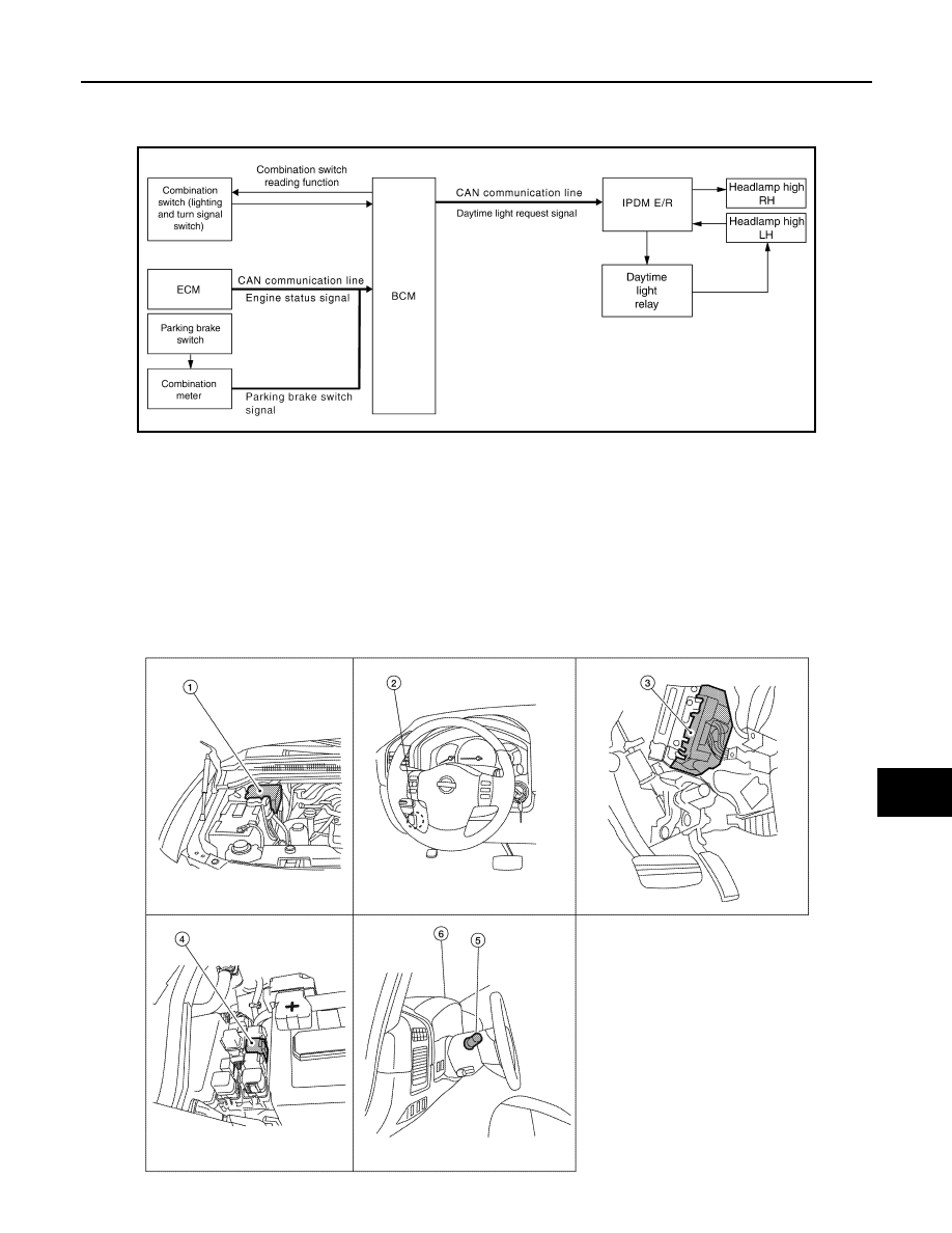
System Diagram
INFOID:0000000006178991
System Description
INFOID:0000000006607843
The headlamp system for Canada vehicles is equipped with a daytime light relay that activates the high beam
headlamps at approximately half illumination whenever the engine is operating. If the parking brake is applied
before the engine is started the daytime lights will not be illuminated. The daytime lights will illuminate once the
parking brake is released. Thereafter, the daytime lights will continue to operate when the parking brake is
applied.
Component Parts Location
INFOID:0000000006178993
AWLIA1751GB
ALLIA0380ZZ