Nissan Titan A60. Manual - part 488
HEADLAMP
EXL-7
< SYSTEM DESCRIPTION >
C
D
E
F
G
H
I
J
K
M
A
B
EXL
N
O
P
SYSTEM DESCRIPTION
HEADLAMP
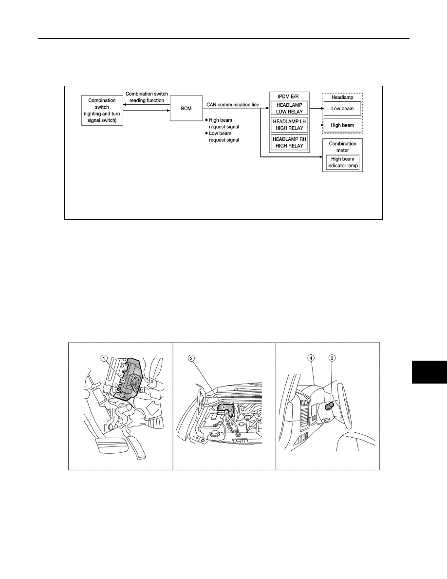
System Diagram
INFOID:0000000006178983
System Description
INFOID:0000000006178984
Control of the headlamp system operation is dependent upon the position of the combination switch (lighting
and turn signal switch). When the combination switch (lighting and turn signal switch) is placed in the 2nd posi-
tion, the BCM (body control module) receives input requesting the headlamps and park lamps to illuminate.
This input is communicated to the IPDM E/R (intelligent power distribution module engine room) via the CAN
communication lines. The CPU (central processing unit) of the IPDM E/R controls the headlamp LH high,
headlamp RH high and headlamp low relay coils. When energized, these relays direct power to the respective
headlamps, which then illuminate.
Component Parts Location
INFOID:0000000006178985
Component Description
INFOID:0000000006178986
LOW BEAM OPERATION
AWLIA1715GB
1.
BCM M18, M20 (view with instrument
panel removed)
2.
IPDM E/R E122, E123, E124
3.
Combination switch (lighting and turn-
signal switch) M28
4.
Combination meter M24
ALLIA0379ZZ