Nissan Versa Note. Manual - part 581


  Index      Nissan     Nissan Versa Note (2014 year) - Service and Repair Manual


Search            


Content   ..  579  580  581  582   ..


Nissan Versa Note. Manual - part 581


DOOR MIRROR REAR FINISHER

MIR-17

< REMOVAL AND INSTALLATION >

C

D

E

F

G

H

I

J

K

M

A

B

MIR

N

O

P

DOOR MIRROR REAR FINISHER

Removal and Installation

INFOID:0000000008968547

REMOVAL

1. Remove door mirror glass.
a. Tilt the door mirror glass upward.
b. Remove door mirror glass by placing a suitable tool in the recesses between door mirror glass and actua-

tor and rotating (twisting) to releasing the pawls. 

2. Disconnect the harness connector (if equipped) from the door mirror glass.
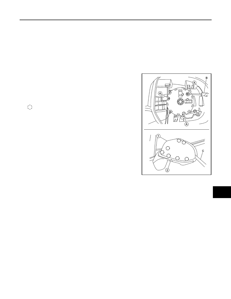
3. Remove actuator screws (A) using a suitable tool (B) and

remove actuator.

NOTE:

Actuator is removed only to access door mirror rear finisher

pawls. It is not a serviceable component. 

4. Release pawls using a suitable tool (C) and remove door mirror

rear finisher (1) from the door mirror (2).

: Pawl

INSTALLATION

Installation is in the reverse order of removal.

CAUTION:

Visually check door mirror rear finisher pawls for deformation and damage during installation. 

AWLIA2179ZZ

MIR-18

< REMOVAL AND INSTALLATION >

DOOR MIRROR REMOTE CONTROL SWITCH

DOOR MIRROR REMOTE CONTROL SWITCH

Removal and Installation

INFOID:0000000008968548

REMOVAL

1. Remove the instrument lower panel LH. Refer to 

IP-15, "Removal and Installation"

.

2. Remove door mirror remote control switch (1) from the instru-

ment lower panel LH using a suitable tool.

: Pawl

INSTALLATION

Installation is in the reverse order of removal.

AWLIA2157ZZ

MWI

MWI-1

DRIVER INFORMATION & MULTIMEDIA

C

D

E

F

G

H

I

J

K

L

M

B

SECTION 

MWI

A

O

P

CONTENTS

METER, WARNING LAMP & INDICATOR

PRECAUTION ...............................................

3

PRECAUTIONS ...................................................

3

Precaution for Supplemental Restraint System 
(SRS) "AIR BAG" and "SEAT BELT PRE-TEN-
SIONER" .................................................................
..

3

PREPARATION ............................................

4

PREPARATION ...................................................

4

Commercial Service Tools  ........................................

4

SYSTEM DESCRIPTION  ..............................

5

COMPONENT PARTS  ........................................

5

METER SYSTEM .........................................................

5

METER SYSTEM : Component Parts Location  ........

5

METER SYSTEM : Combination Meter  ....................

6

SYSTEM ..............................................................

7

METER SYSTEM .........................................................

7

METER SYSTEM : System Description ....................

7

METER SYSTEM : Fail-safe .....................................

8

SPEEDOMETER ..........................................................

9

SPEEDOMETER : System Description .....................

9

TACHOMETER ............................................................

9

TACHOMETER : System Description .......................

9

SHIFT POSITION INDICATOR ....................................

9

SHIFT POSITION INDICATOR : System Descrip-
tion ..........................................................................

10

OIL PRESSURE WARNING LAMP ...........................

10

OIL PRESSURE WARNING LAMP : System De-
scription ...................................................................

10

METER ILLUMINATION CONTROL  .........................

10

METER ILLUMINATION CONTROL : System De-
scription ...................................................................

10

INFORMATION DISPLAY ..........................................

11

INFORMATION DISPLAY : System Description  .....

11

OPERATION .....................................................

13

Switch Name and Function ......................................

13

DIAGNOSIS SYSTEM (COMBINATION 
METER) .............................................................

14

On Board Diagnosis Function ..................................

14

CONSULT Function .................................................

15

ECU DIAGNOSIS INFORMATION ..............

18

COMBINATION METER  ...................................

18

Reference Value ......................................................

18

Fail-safe ...................................................................

20

DTC Index  ...............................................................

21

BCM (BODY CONTROL MODULE)  .................

22

List of ECU Reference .............................................

22

WIRING DIAGRAM ......................................

23

METER SYSTEM  ..............................................

23

Wiring Diagram ........................................................

23

BASIC INSPECTION  ...................................

36

DIAGNOSIS AND REPAIR WORK FLOW  .......

36

Work Flow ................................................................

36

DTC/CIRCUIT DIAGNOSIS  .........................

37

U1000 CAN COMM CIRCUIT  ...........................

37

DTC Logic ................................................................

37

Diagnosis Procedure ..............................................

37

U1010 CONTROL UNIT (CAN) .........................

38

Description ...............................................................

38

DTC Logic ................................................................

38

Diagnosis Procedure  ...............................................

38

B2205 VEHICLE SPEED ..................................

39

MWI-2

Description ..............................................................

39

DTC Logic ...............................................................

39

Diagnosis Procedure .............................................

39

B2267 ENGINE SPEED .....................................

40

Description ..............................................................

40

DTC Logic ...............................................................

40

Diagnosis Procedure  ..............................................

40

B2268 WATER TEMP ........................................

41

Description ..............................................................

41

DTC Logic ...............................................................

41

Diagnosis Procedure  ..............................................

41

POWER SUPPLY AND GROUND CIRCUIT  .....

42

COMBINATION METER  ...........................................

42

COMBINATION METER : Diagnosis Procedure  ....

42

BCM (BODY CONTROL SYSTEM) (WITH INTEL-
LIGENT KEY SYSTEM)  ...........................................
.

42

BCM (BODY CONTROL SYSTEM) (WITH INTEL-
LIGENT KEY SYSTEM) : Diagnosis Procedure  ....
.

42

BCM (BODY CONTROL SYSTEM) (WITHOUT IN-
TELLIGENT KEY SYSTEM)  ....................................
.

43

BCM (BODY CONTROL SYSTEM) (WITHOUT 
INTELLIGENT KEY SYSTEM) : Diagnosis Proce-
dure .......................................................................
.

43

FUEL LEVEL SENSOR SIGNAL CIRCUIT  .......

45

Description ..............................................................

45

Component Function Check  ...................................

45

Diagnosis Procedure .............................................

45

Component Inspection ............................................

46

WASHER FLUID LEVEL SWITCH CIRCUIT  ....

47

Description ..............................................................

47

Diagnosis Procedure  ..............................................

47

Component Inspection ............................................

47

SYMPTOM DIAGNOSIS  .............................

48

THE FUEL GAUGE INDICATOR DOES NOT 
OPERATE ..........................................................

48

Description ..............................................................

48

Diagnosis Procedure ...............................................

48

THE OIL PRESSURE WARNING LAMP 
DOES NOT TURN ON .......................................

49

Description ..............................................................

49

Diagnosis Procedure ...............................................

49

THE OIL PRESSURE WARNING LAMP 
DOES NOT TURN OFF .....................................

50

Description ..............................................................

50

Diagnosis Procedure ...............................................

50

THE DOOR OPEN WARNING CONTINUES 
DISPLAYING, OR DOES NOT DISPLAY  .........

51

Description ..............................................................

51

Diagnosis Procedure ...............................................

51

THE PARKING BRAKE RELEASE WARNING 
CONTINUES DISPLAYING, OR DOES NOT 
DISPLAY ............................................................

52

Description ..............................................................

52

Diagnosis Procedure ...............................................

52

THE LOW WASHER FLUID WARNING CON-
TINUES DISPLAYING, or DOES NOT DIS-
PLAY ..................................................................

53

Description ..............................................................

53

Diagnosis Procedure ...............................................

53

UNIT REMOVAL AND INSTALLATION  ....

54

COMBINATION METER ....................................

54

Removal and Installation .........................................

54

UNIT DISASSEMBLY AND ASSEMBLY ...

55

COMBINATION METER ....................................

55

Exploded View  ........................................................

55

Disassembly and Assembly  ....................................

55


Content   ..  579  580  581  582   ..