Nissan Versa Note. Manual - part 494


  Index      Nissan     Nissan Versa Note (2014 year) - Service and Repair Manual


Search            


Content   ..  492  493  494  495   ..


Nissan Versa Note. Manual - part 494


COMPONENT PARTS

HAC-11

< SYSTEM DESCRIPTION >

[MANUAL AIR CONDITIONING]

C

D

E

F

G

H

J

K

L

M

A

B

HAC

N

O

P

SYSTEM DESCRIPTION

COMPONENT PARTS

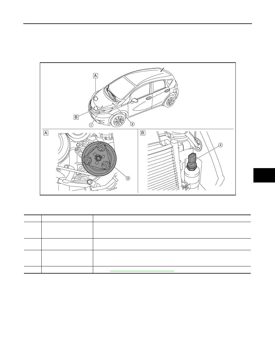
Component Parts Location

INFOID:0000000009549322

A.

RH front of engine compartment

B.

Behind LH side of front fascia

No.

Component

Description

1.

ECM

The ECM sends a compressor ON request to the IPDM E/R based on the status of engine 
operation and load as well as refrigerant pressure information. If all the conditions are met for 
A/C operation, the ECM transmits the compressor ON request to the IPDM E/R.

2.

IPDM E/R

A/C relay is integrated in IPDM E/R. IPDM E/R operates A/C relay when receiving A/C com-
pressor request signal from ECM via CAN communication line.

3.

A/C compressor

Vaporized refrigerant is drawn into the A/C compressor from the evaporator, where it is com-
pressed to a high pressure, high temperature vapor. The hot, compressed vapor is then dis-
charged to the condenser.

4.

Refrigerant pressure sensor

Refer to 

EC-27, "Refrigerant Pressure Sensor"

.

ALIIA0811ZZ

HAC-12

< SYSTEM DESCRIPTION >

[MANUAL AIR CONDITIONING]

COMPONENT PARTS

A.

LH side of instrument panel

B.

Behind center of instrument panel

C.

Center of instrument panel

No.

Component

Description

1.

BCM

The BCM receives the fan ON and A/C ON signals from the front air control and sends a com-
pressor ON request to the ECM. 

2.

Fuse Block (J/B)

Located in the passenger compartment, behind the left lower IP, the Fuse Block (J/B) con-
tains the front blower motor relay and several fuses required for the air conditioner control 
system.

3.

Blower relay

The blower relay controls the flow of current to fuse 20, 21 and 22 in the Fuse Block (J/B). 
The relay is connected directly to ground, and is energized when the ignition switch is in the 
ON or START position.

4.

Front blower motor

The front blower motor varies the speed at which the air flows through the ventilation system. 

5.

Front blower motor resistor

Ground for the blower is supplied through blower resistor and the blower speed switch. As 
the switch is moved from position 1 through 4, more current is allowed to flow through the 
motor, for a higher speed. This is because less resistors are in the path as the switch is 
moved to a higher position. When the switch is on the highest position, all resistors are by-
passed. 

6.

Thermo control amp.

Thermo control amp. is composed of thermistor and amplifier. When the A/C switch signal is 
received from the front air control, the thermo control amp. transmits the A/C ON signal to the 
BCM according to evaporator fin temperature. When the thermistor detecting temperature of 
the air that passes through evaporator is extremely low, the thermo control amp. sends the 
A/C OFF signal to BCM, and stops the compressor.

7.

Front air control

The front air control controls the operation of the A/C and heating system.

ALIIA0812ZZ

SYSTEM

HAC-13

< SYSTEM DESCRIPTION >

[MANUAL AIR CONDITIONING]

C

D

E

F

G

H

J

K

L

M

A

B

HAC

N

O

P

SYSTEM

System Description

INFOID:0000000009549323

SYSTEM DIAGRAM

SYSTEM DESCRIPTION

• The manual air conditioning system is controlled by a sequence of functions from the front air control, BCM,

ECM, and IPDM E/R.

• The fan speed of the front blower motor is changed by the combination of the fan control dial (fan switch)

operation and blower resistor control.

Compressor Control

INFOID:0000000009549324

PRINCIPLE OF OPERATION

Compressor is not activated.

Functional Circuit Diagram

ALIIA0813GB

Module/Function

Door control

A/C request signal

Compressor control

Cooling fan control

Front air control

HAC-15

HAC-13

BCM

BCS-7

 (With Intelligent Key)

BCS-74

 (Without Intelligent Key)

ECM

HAC-13

EC-38

IPDM E/R

HAC-13

EC-38

HAC-14

< SYSTEM DESCRIPTION >

[MANUAL AIR CONDITIONING]

SYSTEM

Functional Initial Inspection Chart

×: Applicable

DESCRIPTION

• When A/C switch signal is received from front air control, the thermo control amp. transmits A/C ON signal to

the BCM according to evaporator fin temperature.

• When the front blower motor is operated, the front air control transmits blower fan ON signal to the BCM.

• BCM transmits the A/C ON signal and blower fan ON signal to ECM via CAN communication line. Refer to

LAN-24, "CAN COMMUNICATION SYSTEM : System Description"

• ECM judges the conditions of each sensor (Refrigerant pressure sensor signal, accelerator position signal,

etc.), and transmits the A/C compressor request signal to IPDM E/R via CAN communication line.

• By receiving the A/C compressor request signal from ECM, IPDM E/R turns the A/C relay to ON, and acti-

vates the compressor. Refer to 

PCS-6, "RELAY CONTROL SYSTEM : System Description"

 (with Intelligent

Key) or 

PCS-35, "RELAY CONTROL SYSTEM : System Description"

 (without Intelligent Key)

L (1)

: Fan ON signal

CAN (1)

: A/C ON signal

L (2)

: A/C switch signal

: Blower fan ON signal

L (3)

: Defroster position switch 2

CAN (2)

: A/C compressor request signal

L (4)

: Thermo control amp. ON signal

: A/C compressor feedback signal

JPIIA1661GB

Control unit

Diagnosis item

Location

A

B

C

D

E

BCM

“BCM-AIR COND”

Self-diagnosis

×

Data monitor

×

ECM

“ENGINE”

Self-diagnosis
(CAN communication line)

×

Data monitor

×

×

IPDM E/R

“IPDM E/R”

Self-diagnosis
(CAN communication line)

×

Data monitor

×

Auto active test

×


Content   ..  492  493  494  495   ..