Nissan Versa Note. Manual - part 455
EVAP CONTROL SYSTEM PRESSURE SENSOR
FL-19
< REMOVAL AND INSTALLATION >
C
D
E
F
G
H
I
J
K
L
M
A
FL
N
P
O
EVAP CONTROL SYSTEM PRESSURE SENSOR
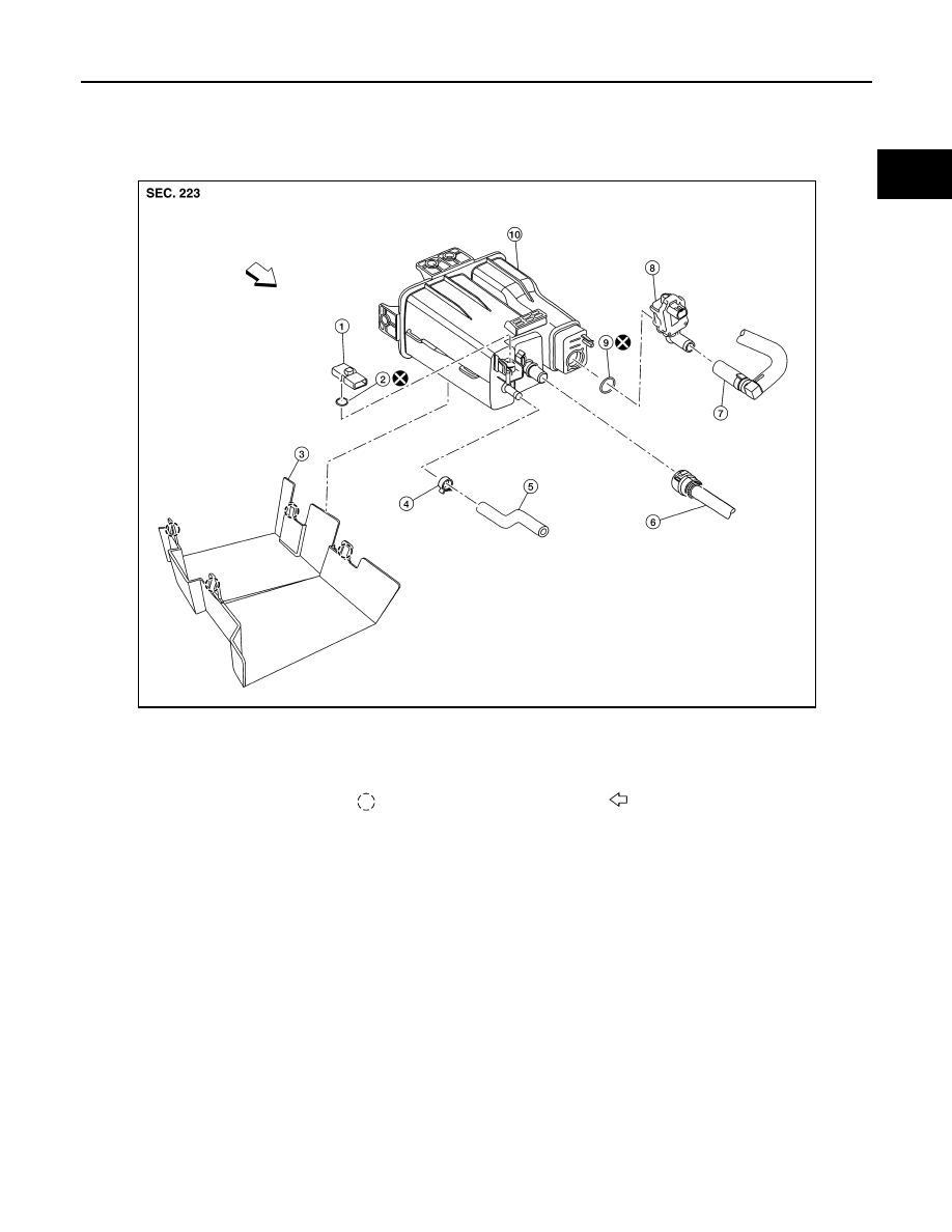
Exploded View
INFOID:0000000009445756
Removal and Installation
INFOID:0000000009445757
NOTE:
The EVAP canister vent control valve and EVAP canister system pressure sensor can be removed without
removing the EVAP canister.
REMOVAL
1. Disconnect EVAP canister control system pressure sensor harness connector.
2. Remove EVAP canister control system pressure sensor and O-ring.
INSTALLATION
Installation is in the reverse order of removal.
CAUTION:
Do not reuse O-ring.
1.
EVAP control system pressure sensor 2.
O-ring
3.
EVAP canister protector
4.
Hose clamp
5.
EVAP canister purge hose
6.
EVAP vent line
7.
EVAP canister vent control valve hose 8.
EVAP canister vent control valve
9.
O-ring
10. EVAP canister
Pawl
Front
AWBIA1593ZZ