Nissan Versa Note. Manual - part 250
HOOD LOCK
DLK-285
< REMOVAL AND INSTALLATION >
[WITHOUT INTELLIGENT KEY SYSTEM]
C
D
E
F
G
H
I
J
L
M
A
B
DLK
N
O
P
HOOD LOCK
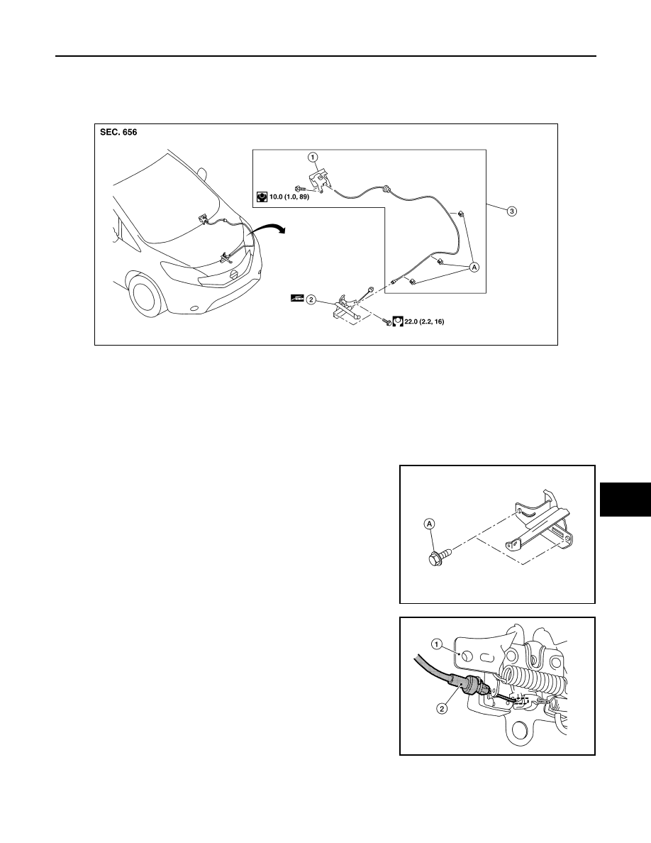
Exploded View
INFOID:0000000009645197
HOOD LOCK
HOOD LOCK : Removal and Installation
INFOID:0000000009645198
REMOVAL
1. Remove hood lock bolts (A).
2. Disconnect hood lock release cable (2) from hood lock (1) and
remove.
INSTALLATION
Installation is in the reverse order of removal.
CAUTION:
1.
Hood lock/fuel filler lid release handle
2.
Hood lock assembly
3.
Hood lock release cable assembly
A.
Clip
AWKIA2572ZZ
ALKIA3190ZZ
AWKIA2497ZZ