Nissan Versa Note. Manual - part 115


  Index      Nissan     Nissan Versa Note (2014 year) - Service and Repair Manual


Search            


Content   ..  113  114  115  116   ..


Nissan Versa Note. Manual - part 115


BRC-24

< SYSTEM DESCRIPTION >

[VDC/TCS/ABS]

SYSTEM

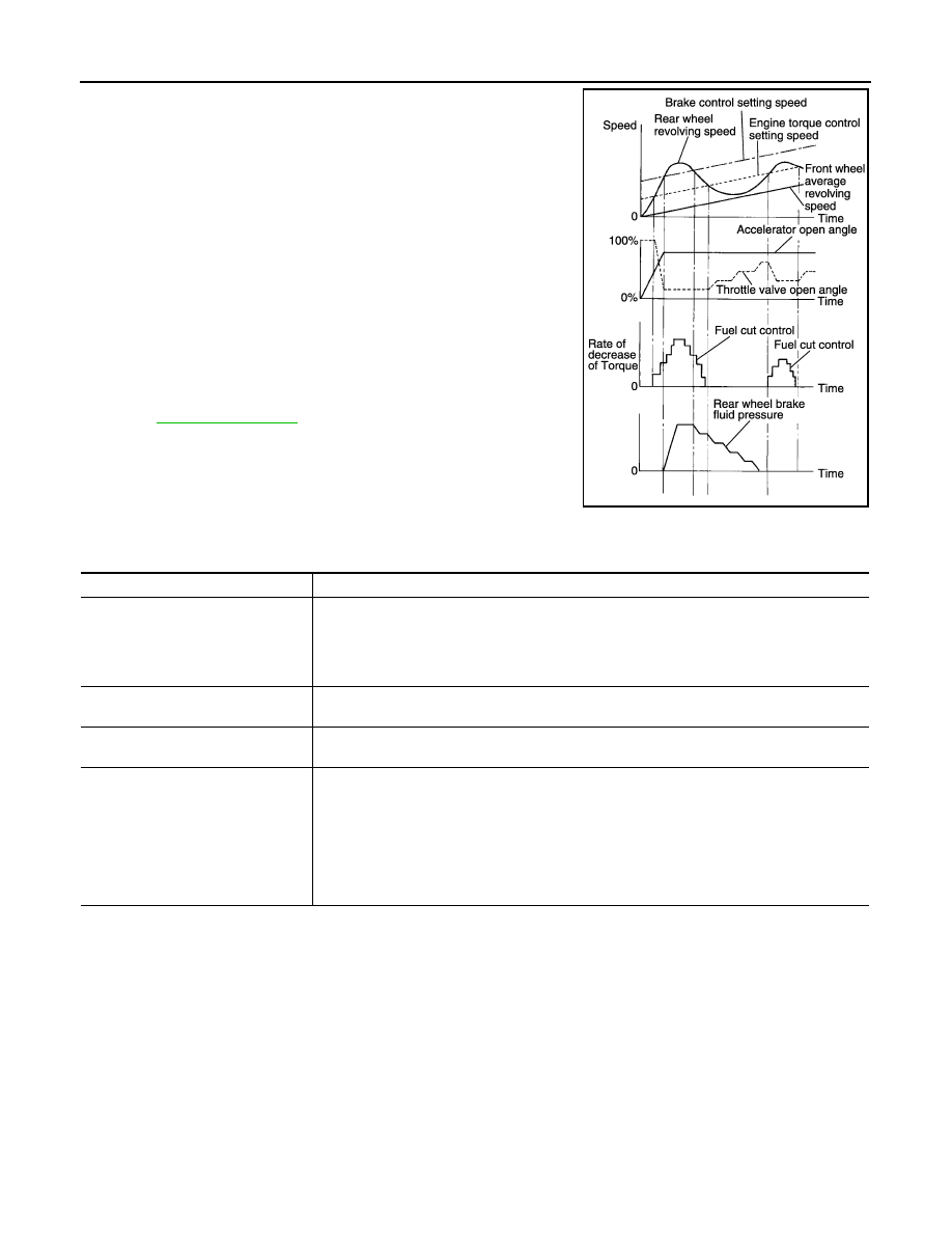
• Wheel spin status of drive wheel is detected by wheel sensor of 4

wheels. Engine output and transmission shift status is controlled

so that slip rate of drive wheels is in appropriate level. When wheel

spin occurs on drive wheel, ABS actuator and electric unit (control

unit) perform brake force control of LH and RH drive wheels (apply

brake force by increasing brake fluid pressure of drive wheel) and

decrease engine torque by engine torque control. Wheel spin

amount decreases. Engine torque is controlled to appropriate

level.

• TCS function can be switched to non-operational status (OFF) by

operating VDC OFF switch. In this case, VDC OFF indicator lamp

turns ON.

• SLIP indicator lamp blinks while TCS function is in operation and

indicates to the driver that the function is in operation.

• CONSULT can be used to diagnose the system.

• Fail-safe function is adopted. When a malfunction occurs in TCS

function, the control is suspended for VDC function and TCS func-

tion. However, ABS function and EBD function operate normally.

Refer to 

BRC-38, "Fail-safe"

.

INPUT SIGNAL AND OUTPUT SIGNAL

Major signal transmission between each unit via communication lines is shown in the following table.

JPFIC0139GB

Component

Signal description

ECM

Transmits the following signals to ABS actuator and electric unit (control unit) via CAN commu-
nication.
• Accelerator pedal position signal
• Engine speed signal
• Target throttle position signal

TCM

Transmits the current gear position signal to ABS actuator and electric unit (control unit) via 
CAN communication.

Steering angle sensor

Transmits the steering angle sensor signal to ABS actuator and electric unit (control unit) via 
CAN communication.

Combination meter

Transmits the following signals to ABS actuator and electric unit (control unit) via CAN commu-
nication.
• Brake fluid level switch signal
• Parking brake switch signal
Receives the following signals from ABS actuator and electric unit (control unit) via CAN com-
munication.
• VDC OFF indicator lamp signal
• SLIP indicator lamp signal

SYSTEM

BRC-25

< SYSTEM DESCRIPTION >

[VDC/TCS/ABS]

C

D

E

G

H

I

J

K

L

M

A

B

BRC

N

O

P

VDC/TCS/ABS : ABS Function

INFOID:0000000009364892

SYSTEM DIAGRAM

• By preventing wheel lock through brake force (brake fluid pressure) control that is electronically controlled by

detecting wheel speed during braking, stability during emergency braking is improved so that obstacles can

be easily bypassed by steering operation.

• During braking, control units calculate wheel speed and pseudo-vehicle speed, and transmit pressure

increase, hold or decrease signals to actuator portion according to wheel slip status.

• The following effects are obtained by preventing wheel lock during

braking.

- Vehicle tail slip is prevented during braking when driving straight.

- Understeer and oversteer tendencies are moderated during brak-

ing while cornering.

- Obstacles may be easily bypassed by steering operation during

braking.

• CONSULT can be used to diagnose the system.

• Fail-safe function is adopted. When a malfunction occurs in ABS

function, the control is suspended for VDC function, TCS function

and ABS function. However, EBD function operates normally.

Refer to 

BRC-27, "VDC/TCS/ABS : Fail-safe"

.

INPUT SIGNAL AND OUTPUT SIGNAL

AWFIA0808GB

JPFIC0140GB

BRC-26

< SYSTEM DESCRIPTION >

[VDC/TCS/ABS]

SYSTEM

Major signal transmission between each unit via communication lines is shown in the following table.

VDC/TCS/ABS : EBD Function

INFOID:0000000009364893

SYSTEM DIAGRAM

• By preventing rear wheel slip increase through rear wheel brake force (brake fluid pressure) control that is

electronically controlled when slight skip on front and rear wheels are detected during braking, stability dur-

ing braking is improved.

• EBD function is expanded and developed from conventional ABS function and corrects rear wheel brake

force to appropriate level by electronic control according to load weight (number of passengers).

Component

Signal description

Combination meter

Receives the following signals from ABS actuator and electric unit (control unit) via CAN com-
munication.
• VDC warning lamp signal
• ABS warning lamp signal

AWFIA0808GB

JPFIC0142GB

SYSTEM

BRC-27

< SYSTEM DESCRIPTION >

[VDC/TCS/ABS]

C

D

E

G

H

I

J

K

L

M

A

B

BRC

N

O

P

• During braking, control unit portion compares slight slip on front

and rear wheels by wheel speed sensor signal, transmits drive sig-

nal to actuator portion when rear wheel slip exceeds front wheel

slip for the specified value or more, and controls rear wheel brake

force (brake fluid pressure) so that increase of rear wheel slip is

prevented and slips on front wheel and rear wheel are nearly

equalized. ABS control is applied when slip on each wheel

increases and wheel speed is the threshold value of ABS control or

less.

• CONSULT can be used to diagnose the system.

• Fail-safe function is adopted. When a malfunction occurs in EBD

function, the control is suspended for VDC function, TCS function,

ABS function and EBD function. Refer to 

BRC-27, "VDC/TCS/ABS

: Fail-safe"

.

INPUT SIGNAL AND OUTPUT SIGNAL

Major signal transmission between each unit via communication lines is shown in the following table.

VDC/TCS/ABS : Fail-safe

INFOID:0000000009364894

VDC AND TCS FUNCTIONS

VDC warning lamp in combination meter turns ON when a malfunction occurs in system [ABS actuator and

electric unit (control unit)]. The control is suspended for VDC and TCS functions. However, ABS and EBD

functions operate normally.

ABS FUNCTION

ABS warning lamp and SLIP indicator lamp in combination meter turn ON when a malfunction occurs in sys-

tem [ABS actuator and electric unit (control unit)]. The control is suspended for VDC, TCS and ABS functions.

However, EBD functions operate normally.

EBD FUNCTION

ABS warning lamp, brake warning lamp and SLIP indicator lamp in combination meter turn ON when a mal-

function occurs in system [ABS actuator and electric unit (control unit)]. The control is suspended for VDC,

TCS, ABS and EBD functions.

JPFIC0143GB

Component

Signal description

Combination meter

Receives the following signals from ABS actuator and electric unit (control unit) via CAN com-
munication.
• ABS warning lamp signal
• Brake warning lamp signal
• SLIP indicator lamp signal


Content   ..  113  114  115  116   ..