Nissan Versa Note. Manual - part 77
BCS
BCM
BCS-45
< ECU DIAGNOSIS INFORMATION >
[WITH INTELLIGENT KEY SYSTEM]
C
D
E
F
G
H
I
J
K
L
B
A
O
P
N
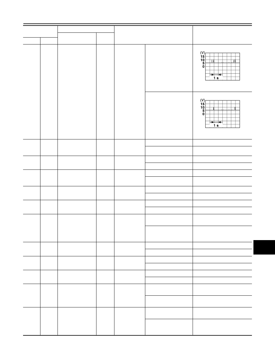
89
(LG)
Ground
Inside key antenna
(trunk room) -
Output
Push-button ig-
nition switch ON
Intelligent Key not in an-
tenna detection area
(Approx. 2 m)
Intelligent Key in antenna
detection area
(80 cm or less)
90
(W)
Ground
Push-button ignition
switch illumination
power supply
Output
Push-button ig-
nition switch il-
lumination
ON
Battery voltage
OFF
0 – 1.5 V
91
(V)
Ground
ACC/ON indicator
lamp
Output
Push-button ig-
nition switch
OFF
Battery voltage
ACC or ON
0 – 1.5 V
92
(B)
Ground
Push-button ignition
switch illumination
lamp
Output
Push-button ig-
nition switch il-
lumination
ON
5.5 V
OFF
0 – 1.5 V
93
(R)
Ground
Intelligent Key warn-
ing buzzer
Output
Intelligent Key
warning buzzer
Sounding
0 – 1.5 V
Not sounding
Battery voltage
96
(SB)
Ground
Accessory relay
control
Output
Ignition Push-
button switch
OFF
0 – 0.5 V
ACC or ON
Battery voltage
97
(R/Y)
Ground Starter relay control
Output
Push-button ig-
nition switch ON
Selector lever in P (Park)
or N (Neutral) position
Battery voltage
Selector lever not in P
(Park) or N (Neutral) posi-
tion
0 – 0.5 V
98
(O)
Ground
Ignition relay (IPDM
E/R) control
Output
Push-button ig-
nition switch
OFF or ACC
Battery voltage
ON
0 – 0.5 V
99
(GR)
Ground
Ignition relay (F/B)
control
Output
Push-button ig-
nition switch
OFF or ACC
0 – 0.5 V
ON
Battery voltage
100
(L)
Ground
Request sw (AS)
signal
Input
Passenger door
request switch
ON (Pressed)
0 – 1.5 V
OFF (Not pressed)
Battery voltage
101
(V)
Ground
Clutch interlock
switch
Input
Clutch interlock
switch
OFF (clutch pedal is not
depressed)
0V
ON (clutch pedal is de-
pressed)
Battery voltage
102
(BR)
Ground P/N position
Input
Selector lever
Selector lever in P (Park)
or N (Neutral) position
Battery voltage
Selector lever not in P
(Park) or N (Neutral) posi-
tion
0 – 1.5 V
Terminal No.
(Wire color)
Description
Condition
Value
(Approx.)
Signal name
Input/
Output
+
−
JMKIA5951GB
JMKIA3839GB