Nissan Versa Note. Manual - part 34
AV-128
< REMOVAL AND INSTALLATION >
[DISPLAY AUDIO]
ANTENNA FEEDER
ANTENNA FEEDER
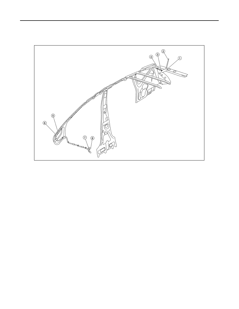
Feeder Layout
INFOID:0000000009541284
1.
Antenna base (antenna amp. and
satellite antenna)
2.
Rod Antenna
3.
M351
4.
M352
5.
M110, M353
6.
M67, M350
7.
M106
8.
M105
ALNIA1520ZZ