Nissan Versa Sedan. Manual - part 848


  Index      Nissan     Nissan Versa Sedan (2014 year) - Service and Repair Manual


Search            


Content   ..  846  847  848  849   ..


Nissan Versa Sedan. Manual - part 848


TM-298

< SYSTEM DESCRIPTION >

[CVT: RE0F11A]

DIAGNOSIS SYSTEM (TCM)
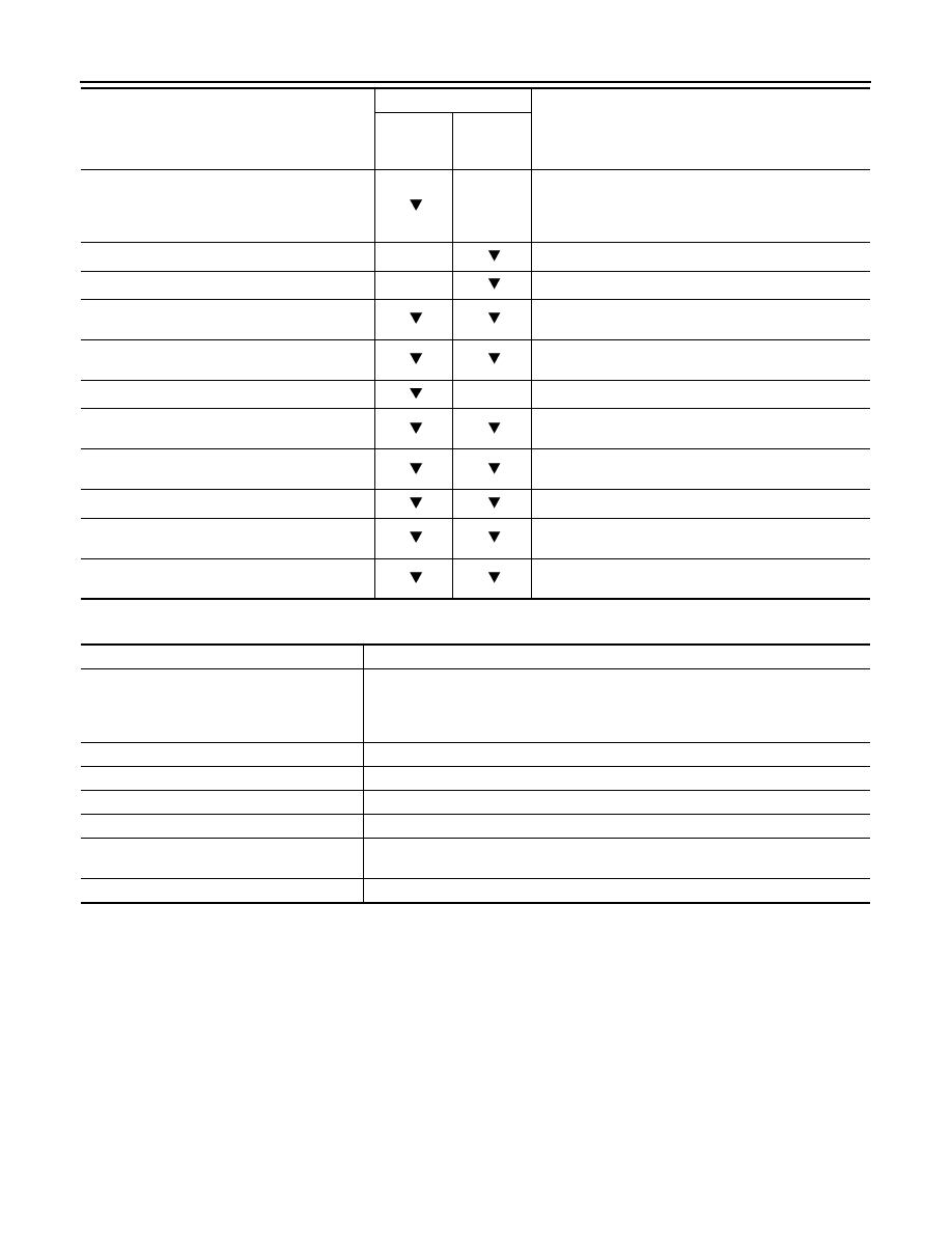
WORK SUPPORT

*: “Clutch point learning” can be selected, but do not use it.

Engine brake adjustment

Check the degradation level of the CVT fluid.

4WD-TCS SIGNAL

(On/Off)

×

• Displays the reception status of the engine torque 

down request signal received through CAN communi-
cation.

• It is displayed although not equipped.

RANGE

×

Displays the gear position recognized by TCM.

M GEAR POS

×

Display the target gear of manual mode

G SEN SLOPE

 (%) 

Displays the gradient angle calculated from the G sensor 
signal voltage.

ENGBRKLVL

(On/Off)

Displays the setting of “ENGINE BRAKE ADJ” in “Work 
Support”.

PVIGN VOLT

(V)

×

Displays the backup voltage of TCM.

TRGT AUX GR RATIO

Displays the target gear ratio of the auxiliary gearbox cal-
culated from processing of gear shift control.

G SEN CALIBRATION

(YET/DONE)

Displays the status of “G SENSOR CALIBRATION” in 
“Work Support”.

N IDLE STATUS

(On/Off)

Displays idle neutral status.

CVT-B

• Displays CVT fluid temperature count.
• This monitor item does not use.

CVT-A

• Displays CVT fluid temperature count.
• This monitor item does not use.

Monitored item

(Unit)

Monitor item selection

Remarks

MAIN SIG-

NALS

ECU IN-

PUT SIG-

NALS 

Item name

Description

ENGINE BRAKE ADJ.

Although there is no malfunction on the transaxle and the CVT system, if a customer 
make a complaint like “I do not feel comfortable with automatic operation of the engine 
brake on downhill”, the engine brake may be cancelled with “engine brake adjust-
ment”.

CONFORM CVTF DETERIORTN

Check the degradation level of the CVT fluid under severe conditions. 

G SENSOR CALIBRATION

Compensate the G sensor. 

ERASE CALIBRATION DATA

Erase the calibration data memorized by TCM.

ERASE LEARNING VALUE 

Erase the learning value memorized by TCM.

ERASE MEMORY DATA 

Perform “erasing of the calibration data” and “erasing of the learned value” at the same 
time.

CLUTCH POINT LEARNING*

Allow learning of the clutch engagement point of the auxiliary gearbox for TCM.

ENGINE BRAKE LEVEL
ON

: Turn ON the engine brake control.

OFF

: Turn OFF the engine brake control.

CVTF degradation level data
210,000 or more

: Replacement of the CVT fluid is required.

Less than 210,000

: Replacement of the CVT fluid is not required.

TCM

TM-299

< ECU DIAGNOSIS INFORMATION >

[CVT: RE0F11A]

C

E

F

G

H

I

J

K

L

M

A

B

TM

N

O

P

ECU DIAGNOSIS INFORMATION

TCM

Reference Value

INFOID:0000000009268102

CONSULT DATA MONITOR STANDARD VALUE

• In CONSULT, electric shift timing or lock-up timing, i.e. operation timing of each solenoid valve, is displayed.

Therefore, if there is an obvious difference between the shift timing estimated from a shift shock (or engine

speed variations) and that shown on the CONSULT, the mechanism parts (including the hydraulic circuit)

excluding the solenoids and sensors may be malfunctioning. In this case, check the mechanical parts follow-

ing the appropriate diagnosis procedure.

• Shift point (gear position) displayed on CONSULT slightly differs from shift pattern described in Service Man-

ual. This is due to the following reasons.

- Actual shift pattern may vary slightly within specified tolerances.

- While shift pattern described in Service Manual indicates start of each shift, CONSULT shows gear position

at end of shift.

- The solenoid display (ON/OFF) on CONSULT is changed at the start of gear shifting. In contrast, the gear

position display is changed at the time when gear shifting calculated in the control unit is completed. 

NOTE:

The following table includes information (items) inapplicable to this vehicle. For information (items) applicable

to this vehicle, refer to CONSULT display items.

Monitor item

Condition

Value/Status

VSP SENSOR

While driving

Almost same as the speedometer display. 

ESTM VSP SIG

While driving

Almost same as the speedometer display. 

PRI SPEED SEN

In driving (lock-up ON) 

A value obtained from dividing engine 
speed by counter gear ratio 

SEC REV SENSOR

Auxiliary gearbox: 1GR

Approximately twice the “VHCL/S SE 
(REV)”

Auxiliary gearbox: 2GR

Almost same as the “VHCL/S SE (REV)” 

VHCL/S SE (REV)

Auxiliary gearbox: 1GR

Approximately half of the “SEC REV SEN-
SOR”

Auxiliary gearbox: 2GR

Almost same as the “SEC REV SENSOR”

ENG SPEED SIG

Engine running

Almost same reading as tachometer

LINE PRESSURE SEN

• Selector lever: “N” position
• At  idle

Approx. 0.88 – 0.92 V

ATF TEMP SEN

CVT fluid: Approx. 20

°C (68°F)

Approx. 2.01 – 2.05 V

CVT fluid: Approx. 50

°C (122°F)

Approx. 1.45 – 1.50 V

CVT fluid: Approx. 80

°C (176°F)

Approx. 0.90 – 0.94 V

G SENSOR

Vehicle is level

Approx. 2.5 V

VIGN SEN

Ignition switch: ON

10 – 16 V

VEHICLE SPEED

While driving

Almost same as the speedometer display. 

INPUT REV

In driving (lock-up ON) 

Almost same as the engine speed. 

PRI SPEED

In driving (lock-up ON) 

A value obtained from dividing engine 
speed by counter gear ratio 

SEC SPEED

Auxiliary gearbox: 1GR

Approximately twice the “OUTPUT REV” 

Auxiliary gearbox: 2GR

Almost same as “OUTPUT REV”

OUTPUT REV

Auxiliary gearbox: 1GR

Approximately half of “SEC SPEED”

Auxiliary gearbox: 2GR

Almost same as “SEC SPEED”

ENG SPEED

Engine running

Almost same reading as tachometer

SLIP REV

While driving

Engine speed 

− Input speed

TM-300

< ECU DIAGNOSIS INFORMATION >

[CVT: RE0F11A]

TCM

TOTAL GEAR RATIO

Auxiliary gearbox: 1GR

Counter gear ratio 

×Pulley ratio Auxiliary 

gearbox gear ratio 

Auxiliary gearbox: 2GR

Counter gear ratio 

×Pulley ratio

PULLEY GEAR RATIO

In driving (forward) 

Approx. 2.20 

− 0.55

In driving (reverse) 

Approx. 2.20

AUX GEARBOX

Vehicle started with selector lever in “L” position

1st

Release the accelerator pedal after the follow-
ing conditions are satisfied
• Selector lever: “D” position
• Accelerator pedal position: 1/8 or less
• Vehicle speed: 50 km/h (31 MPH) or more

2nd

In gear shifting of auxiliary gearbox

1st 

⇔ 2nd

G SPEED 

Vehicle stopped

0.00 G

During acceleration

The value changes to the positive side 
along with acceleration. 

During deceleration

The value changes to the positive side 
along with deceleration. 

ACCEL POSI SEN 1

Accelerator pedal released

0.00 deg

Accelerator pedal fully depressed

80.00 deg

VENG TRQ

While driving

The value changes along with acceleration/
deceleration. 

PRI TRQ

While driving

The value changes along with acceleration/
deceleration. 

TRQ RTO

While driving

The value changes along with acceleration/
deceleration. 

LINE PRESSURE

Selector lever: “P” position

Approx. 0.575 MPa

FLUID TEMP

Ignition switch ON.

Displays the CVT fluid temperature. 

DSR REV

While driving

It varies along with the driving condition. 

TRGT GEAR RATIO

While driving

It varies along with the driving condition. 

TGT PLLY GR RATIO

In driving (forward) 

Approx. 2.20 

− 0.55

In driving (reverse) 

Approx. 2.20

TRGT AUX GEARBOX

Vehicle started with selector lever in “L” position

1st

Release the accelerator pedal after the follow-
ing conditions are satisfied
• Selector lever: “D” position
• Accelerator pedal position: 1/8 or less
• Vehicle speed: 50 km/h (31 MPH) or more

2nd

In gear shifting of auxiliary gearbox

Display gear position after gear shifting

LU PRS

• Engine started
• Vehicle is stopped.

Approx. 

−0.500 MPa

• Selector lever: “D” position
• Accelerator pedal position: 1/8 or less
• Vehicle speed: 20 km/h (12 MPH) or more

Approx. 0.450 MPa

LINE PRS

• After engine warm up
• Selector lever: “N” position
• At  idle

Approx. 0.500 MPa

• After engine warming up
• Selector lever: “N” position
• Depress the accelerator pedal fully

Approx. 4.930 – 5.430 MPa

TRGT PRI PRESSURE

• Selector lever: “L” position
• Vehicle speed: 20 km/h (12 MPH)

Approx. 0.325 MPa

Monitor item

Condition

Value/Status

TCM

TM-301

< ECU DIAGNOSIS INFORMATION >

[CVT: RE0F11A]

C

E

F

G

H

I

J

K

L

M

A

B

TM

N

O

P

TRGT HC/RB PRESS

• Selector lever: “L” position
• Vehicle speed: 20 km/h (12 MPH)

Approx. 0.000 MPa

Release the accelerator pedal after the follow-
ing conditions are satisfied
• Selector lever: “D” position
• Accelerator pedal position: 1/8 or less
• Vehicle speed: 50 km/h (31 MPH) or more

Approx. 0.400 MPa

TRGT LB PRESSURE

• Selector lever: “L” position
• Vehicle speed: 20 km/h (12 MPH)

Approx. 0.325 MPa

Release the accelerator pedal after the follow-
ing conditions are satisfied
• Selector lever: “D” position
• Accelerator pedal position: 1/8 or less
• Vehicle speed: 50 km/h (31 MPH) or more

Approx. 0.000 MPa

ISOLT1

• Engine started
• Vehicle is stopped.

Approx. 0.000 A

• Selector lever: “D” position
• Accelerator pedal position: 1/8 or less
• Vehicle speed: 20 km/h (12 MPH) or more

Approx. 0.500 A

ISOLT2 

• After engine warm up
• Selector lever: “N” position
• At  idle

Approx. 0.800 – 0.900 A

• After engine warming up
• Selector lever: “N” position
• Depress the accelerator pedal fully

Approx. 0.350 – 0.400 A

PRI SOLENOID

• Selector lever: “L” position
• Vehicle speed: 20 km/h (12 MPH)

Approx. 0.850 – 0.900 A

HC/RB SOLENOID

• Selector lever: “L” position
• Vehicle speed: 20 km/h (12 MPH)

Approx. 1.000 A

Release the accelerator pedal after the follow-
ing conditions are satisfied
• Selector lever: “D” position
• Accelerator pedal position: 1/8 or less
• Vehicle speed: 50 km/h (31 MPH) or more

Approx. 0.800 – 0.850 A

L/B SOLENOID

• Selector lever: “L” position
• Vehicle speed: 20 km/h (12 MPH)

Approx. 0.200 – 0.250 A

Release the accelerator pedal after the follow-
ing conditions are satisfied
• Selector lever: “D” position
• Accelerator pedal position: 1/8 or less
• Vehicle speed: 50 km/h (31 MPH) or more

Approx. 0.000 A

SOLMON1

• Engine started
• Vehicle is stopped.

Approx. 0.000 A

• Selector lever: “D” position
• Accelerator pedal position: 1/8 or less
• Vehicle speed: 20 km/h (12 MPH) or more

Approx. 0.500 A

SOLMON2

• After engine warm up
• Selector lever: “N” position
• At  idle

Approx. 0.800 – 0.900 A

• After engine warming up
• Selector lever: “N” position
• Depress the accelerator pedal fully

Approx. 0.350 – 0.400 A

PRI SOL MON

• Selector lever: “L” position
• Vehicle speed: 20 km/h (12 MPH)

Approx. 0.850 – 0.900 A

Monitor item

Condition

Value/Status


Content   ..  846  847  848  849   ..