Nissan Versa Sedan. Manual - part 581
MWI
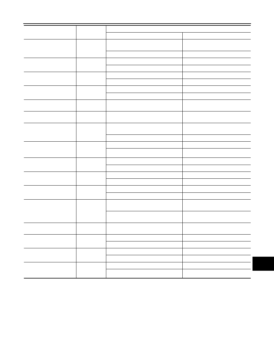
COMBINATION METER
MWI-23
< ECU DIAGNOSIS INFORMATION >
[TYPE A]
C
D
E
F
G
H
I
J
K
L
M
B
A
O
P
*: Displays “OFF” if the brake warning lamp is illuminated when the valve check starts, the parking brake
switch is turned ON or the brake fluid level switch is turned ON.
NOTE:
Some items are not available according to vehicle specification.
REAR DEF SW
Rear defogger
switch
When rear defogger switch is pressed to
ON
On
When rear defogger switch is pressed to Off
Off
BRAKE SW
Brake switch
When brake pedal is applied
On
When brake pedal is released
Off
FUEL W/L
Low fuel warn-
ing
When low fuel warning is ON
On
When low fuel warning is OFF
Off
EPS W/L
EPS warning
lamp
EPS warning lamp ON
On
EPS warning lamp OFF
Off
CHAGE W/L
Charge warn-
ing lamp
Engine running
Off
SHIFT IND
Shift position
indicator
The shift position indicator displayed.
[P, R, N, D, L] (CVT)
[P, R, N, D, 2, 1] (A/T)
FUEL CAP W/L
Loose fuel cap
warning
When the fuel-filler cap is installed incor-
rectly.
On
When the fuel-filler cap is installed correctly.
Off
AIR PRES W/L
Tire pressure
warning lamp
operation
When tire pressure warning lamp is ON
On
When tire pressure warning lamp is OFF
Off
PKB SW
Parking brake
switch
When parking brake is active
On
When parking brake is inactive
Off
BUCKLE SW
Seat belt buck-
le switch LH
When seat belt buckle is unfastened (LH).
On
When seat belt buckle is fastened (LH).
Off
BRAKE OIL SW
Brake fluid level
switch
When brake fluid level switch ON
On
When brake fluid level switch OFF
Off
PASS BUCKLE SW
Seat belt buck-
le switch RH
When passenger seat is occupied and seat
belt buckle is unfastened (RH).
On
When passenger seat is unoccupied and
seat belt buckle is unfastened (RH).
Off
DISTANCE
Distance to
empty
While driving
[km/h or mph]
BUZZER
Buzzer opera-
tion
When Buzzer is ON
On
When Buzzer is OFF
Off
SLIP IND
Slip indicator
lamp
When SLIP indicator lamp is ON.
On
When SLIP indicator lamp is OFF.
Off
VDC/TCS IND
VDC indicator
lamp
When VDC indicator lamp is ON.
On
When VDC indicator lamp is OFF
Off
Monitor Item
Display content
Data monitor
Condition
Reference value in normal operation