Nissan Maxima. Manual - part 214
BCS
DIAGNOSIS AND REPAIR WORKFLOW
BCS-3
< BASIC INSPECTION >
[BCM]
C
D
E
F
G
H
I
J
K
L
B
A
O
P
N
BASIC INSPECTION
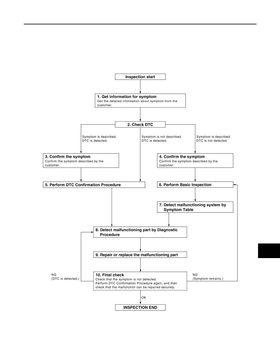
DIAGNOSIS AND REPAIR WORKFLOW
Work Flow
INFOID:0000000009467024
OVERALL SEQUENCE
DETAILED FLOW
JMKIA0101GB