Nissan March K13. Manual - part 467


  Index      Nissan     Nissan March K13 - Service and Repair Manual)


Search            


Content   ..  465  466  467  468   ..


Nissan March K13. Manual - part 467


MWI-6

< SYSTEM DESCRIPTION >

SYSTEM

SYSTEM

METER SYSTEM

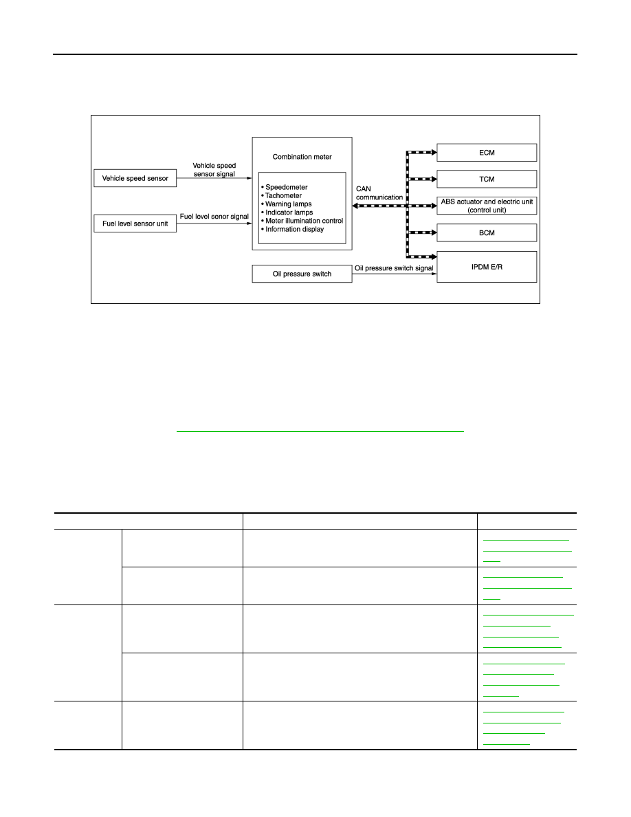
METER SYSTEM : System Diagram

INFOID:0000000005883849

METER SYSTEM : System Description

INFOID:0000000005883850

COMBINATION METER

• The combination meter receives the information required to control the operation of each gauge, indicator/

warning lamp, and information display via CAN communication from each unit, each switch, and sensor.

• The combination meter incorporates a trip computer that displays, warnings and information on the informa-

tion display according to the information received from various units.

• The combination meter incorporates a buzzer function that sounds an audible alarm with the integrated

buzzer device. Refer to 

WCS-6, "WARNING CHIME SYSTEM : System Description"

 for further details.

• The combination meter incorporates a diagnosis function that allows the technician to perform diagnoses

with CONSULT-III.

• The combination meter integrates the meter circuit check function and the segment check function that

checks the information display operation.

METER CONTROL FUNCTION LIST

JSNIA2915GB

System

Description

Reference

Measuring in-
struments

Speedometer

Indicates vehicle speed.

MWI-9, "SPEEDOME-
TER : System Descrip-
tion"

Tachometer (with tachome-
ter)

Indicates engine speed.

MWI-9, "TACHOME-
TER : System Descrip-
tion"

Warning lamp/
indicator lamp

High water temperature 
warning lamp 

Turns ON when engine coolant reaches a high tempera-
ture.

MWI-9, "HIGH WATER 
TEMPERATURE 
WARNING LAMP : 
System Description"

Oil pressure warning lamp

The warning lamp turns ON or turns OFF, according to en-
gine hydraulic pressure.

MWI-10, "OIL PRES-
SURE WARNING 
LAMP : System De-
scription"

Meter illumina-
tion control

Meter illumination control 
function

Turns ON/OFF according to the combination switch (light-
ing switch).

MWI-11, "METER IL-
LUMINATION CON-
TROL : System 
Description"

MWI

SYSTEM

MWI-7

< SYSTEM DESCRIPTION >

C

D

E

F

G

H

I

J

K

L

M

B

A

O

P

ARRANGEMENT OF COMBINATION METER

METER SYSTEM : Fail-Safe

INFOID:0000000005883851

FAIL-SAFE

The combination meter activates the fail-safe control if CAN communication with each unit is malfunctioning.

Information 
display

Gauge 
and 
Meter

Fuel gauge

Displays fuel level.

MWI-11, "INFORMA-
TION DISPLAY : Sys-
tem Description"

Odo/trip meter

Displays vehicle distance.

Shift position indicator (A/T 
models)

Displays shift position.

Trip 
comput-
er

Current fuel con-
sumption

Displays current fuel consumption.

Average fuel con-
sumption

Displays average fuel consumption.

Distance to emp-
ty

Displays distance to empty.

Interrupt 
indica-
tion

Low fuel warning

Displays low fuel warning.

Clock

Displays time.

System

Description

Reference

A.

With tachometer

JSNIA2936ZZ

Function

Specifications

Speedometer (A/T models)

Reset to zero by suspending communication.

Tachometer

Illumination control

When suspending communication, changes to nighttime mode.

Information display

Shift position indicator

The indicator turns OFF by suspending communication.

Instantaneous fuel consumption

• When reception time of an abnormal signal is 2 seconds or 

less, the last received datum is used for calculation to indi-
cate the result.

• When reception time of an abnormal signal is more than two 

seconds, the last result calculated during normal condition is 
indicated.

Average fuel consumption

Possible driving distance

Engine start operation indicator

The indicator turns OFF by suspending communication.

MWI-8

< SYSTEM DESCRIPTION >

SYSTEM

SPEEDOMETER

SPEEDOMETER : System Diagram

INFOID:0000000005883852

MODELS WITH ABS

A/T MODELS WITHOUT ABS

M/T MODELS

Buzzer

The buzzer turns off by suspending communication.

Warning lamp/indicator lamp

ABS warning lamp

The lamp turns ON by suspending communication.

EPS warning lamp

Brake warning lamp (With ABS)

High water temperature warning lamp

The lamp turns OFF by suspending communication.

Malfunction indicator lamp

High beam indicator lamp

Turn signal indicator lamp

Front fog lamp indicator lamp

Door warning lamp

Shift P warning lamp

Key warning lamp

Oil pressure warning lamp

OD OFF indicator lamp

Function

Specifications

JSNIA2973GB

JSNIA2917GB

JSNIA2940GB

MWI

SYSTEM

MWI-9

< SYSTEM DESCRIPTION >

C

D

E

F

G

H

I

J

K

L

M

B

A

O

P

SPEEDOMETER : System Description

INFOID:0000000005883853

MODELS WITH ABS

• The ABS actuator and electric unit (control unit) transmits a vehicle speed signal to the combination meter

via CAN communication.

• The combination meter indicates a vehicle speed to the speedometer, based on the vehicle speed signal

received from the ABS actuator and electric unit.

A/T MODELS WITHOUT ABS

• TCM transmits a vehicle speed signal to the combination meter via CAN communication.
• The combination meter indicates a vehicle speed to the speedometer, based on the vehicle speed signal

received from TCM.

M/T MODELS

• The vehicle speed sensor transmits a vehicle speed sensor signal to the combination meter.
• The combination meter indicates a vehicle speed to the speedometer, based on the vehicle speed sensor

signal received from vehicle speed sensor.

TACHOMETER

TACHOMETER : System Diagram

INFOID:0000000005883854

TACHOMETER : System Description

INFOID:0000000005883855

• ECM converts the pulse signal provided by the crankshaft position sensor to an engine speed signal and

transmits it to the combination meter via CAN communication.

• The combination meter indicates the engine speed to the tachometer according to the engine speed signal

received via CAN communication. 

HIGH WATER TEMPERATURE WARNING LAMP

HIGH WATER TEMPERATURE WARNING LAMP : System Diagram

INFOID:0000000005885479

HIGH WATER TEMPERATURE WARNING LAMP : System Description

INFOID:0000000005885480

• ECM reads the engine coolant temperature signal from the engine coolant temperature sensor and transmits

the signal to the combination meter via CAN communication. 

•  The combination meter turns ON/OFF the high water temperature warning lamp when receiving an engine

coolant temperature signal via CAN communication.

JSNIA2974GB

JSNIA2918GB


Content   ..  465  466  467  468   ..