Nissan Silvia. Manual - part 339


  Index      Nissan     Nissan Silvia - Service Manual (2001 year)


Search            


Content   ..  337  338  339  340   ..


Nissan Silvia. Manual - part 339


SST051C

3.

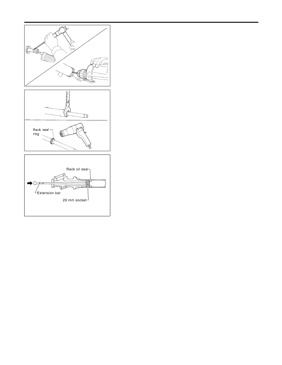
Remove tie-rod outer sockets and boots.

4.

Loosen tie-rod inner socket by prying up staked portion, and
remove socket and spacer ring.

5.

Remove retainer.

6.

Use a 2 to 2.5 mm (0.079 to 0.098 in) diameter drill to com-
pletely remove staked portion of gear housing end.

SST052C

7.

Remove end cover assembly with a suitable tool.

8.

Draw out rack assembly.

9.

Remove rack oil seal (outer).

I

Using a heat gun, heat rack seal ring to approximately 40°C
(104°F).

I

Remove rack seal ring and O-ring.

Be careful not to damage rack.

SST973C

10. Remove rack oil seal (inner) using tape wrapped socket and

extension bar.

Do not scratch inner surfaces of pinion housing.

Inspection

NMST0024

Thoroughly clean all parts in cleaning solvent or Type Dexron

TM

III

or equivalent. Blow dry with compressed air, if available.

BOOT

NMST0024S01

I

Check condition of boot. If cracked excessively, replace it.

I

Check boots for accumulation of power steering fluid.

RACK

NMST0024S02

Thoroughly examine rack gear. If damaged, cracked or worn,
replace it.

GEAR SUB-ASSEMBLY

NMST0024S03

I

Check pinion gear. If it is worn or damaged, replace as a gear
sub-assembly.

I

Manually spin bearing. If torque variations or free play are
noted, replace as a gear sub-assembly.

GEAR HOUSING CYLINDER

NMST0024S04

Check gear housing cylinder bore for scratches or other damage.
Replace if necessary.

POWER STEERING GEAR AND LINKAGE

Disassembly (Cont’d)

ST-18

SST468C

TIE-ROD OUTER AND INNER SOCKETS

NMST0024S05

I

Check ball joints for swinging force.

Tie-rod outer and inner ball joints swinging force “A”:

Refer to SDS, ST-30.

I

Check ball joint for rotating torque.

Tie-rod outer ball joint rotating torque “B”:

Refer to SDS, ST-30.

I

Check ball joints for axial end play.

Tie-rod outer and inner ball joints axial end play “C”:

Refer to SDS, ST-30.

I

Check condition of dust cover. If cracked excessively, replace
outer tie-rod.

SST083B

Assembly

NMST0025

1.

Install O-ring.

2.

Using a heat gun, heat new teflon rack seal ring to approxi-
mately 40°C (104°F). Then place it onto rack.

SST885BC

3.

Using Tool, compress rack seal ring securely onto rack.

Always insert Tool from the rack gear side.

SST201A

4.

Insert new rack oil seal.

I

Place plastic film into rack oil seal to prevent damage by
rack teeth.

I

Do not forget to remove plastic film after rack oil seal is
positioned properly.

I

Make sure lips of rack oil seal face each other.

GI

MA

EM

LC

EC

FE

CL

MT

AT

PD

AX

SU

BR

RS

BT

HA

SC

EL

IDX

POWER STEERING GEAR AND LINKAGE

Inspection (Cont’d)

ST-19

SST971C

5.

Install rack oil seal (Inner) with rack assembly.

SST321B

6.

Insert rack oil seal (Outer) and end cover assembly to rack.
Then install end cover assembly.

JST963C

7.

Install the inner and outer rack oil seal with both lips facing
each other.

8.

Tighten the end cover assembly with the specified torque.

Tightening torque: Refer to “Components”, ST-15.

CAUTION:

Do not damage the rack surface. If the surface is damaged,
replace rack to avoid oil leakage.

SST073B

9.

Fasten end cover assembly to gear housing by staking.

SST086BA

10. Set rack gear in neutral position.

Rack stroke “S”:

Refer to SDS, ST-30.

POWER STEERING GEAR AND LINKAGE

Assembly (Cont’d)

ST-20

SST964C

11. Install O-rings to gear sub-assembly.

I

Discard old O-rings; replace with new ones.

12. Tighten gear sub-assembly securing bolts to specified tighten-

ing torque.

JST965C

13. Ensure that the rack is centered. Install rear cover cap so that

its protrusion is positioned as shown in figure.

SST972C

14. Install adjusting screw temporarily.

SST866C

15. Install lock plate to rack.
a.

Temporarily install spacer ring to rack.

Discard old spacer ring; replace with a new one.
b.

Install lock plate to inner socket.

Discard old lock plate; replace with a new one.
c.

Apply a coat of locking sealant to inner socket threads. Screw
inner socket into rack and tighten to specified torque.

d.

Clinch lock plate at rack groove location (at two points).

e.

Install spacer ring to lock plate as shown in the Figure at left.

Be careful not to damage spacer ring during installation

SST072BB

16. Measure pinion rotating torque within the range of 180° from

neutral position.
Stop the gear at the point of maximum torque.

17. Loosen adjusting screw, then retighten it to 4.9 to 5.9 N·m (50

to 60 kg-cm, 43 to 52 in-lb).

18. Loosen adjusting screw by 60° to 80°.

GI

MA

EM

LC

EC

FE

CL

MT

AT

PD

AX

SU

BR

RS

BT

HA

SC

EL

IDX

POWER STEERING GEAR AND LINKAGE

Assembly (Cont’d)

ST-21


Content   ..  337  338  339  340   ..