Nissan Silvia. Manual - part 309


  Index      Nissan     Nissan Silvia - Service Manual (2001 year)


Search            


Content   ..  307  308  309  310   ..


Nissan Silvia. Manual - part 309


SPD901

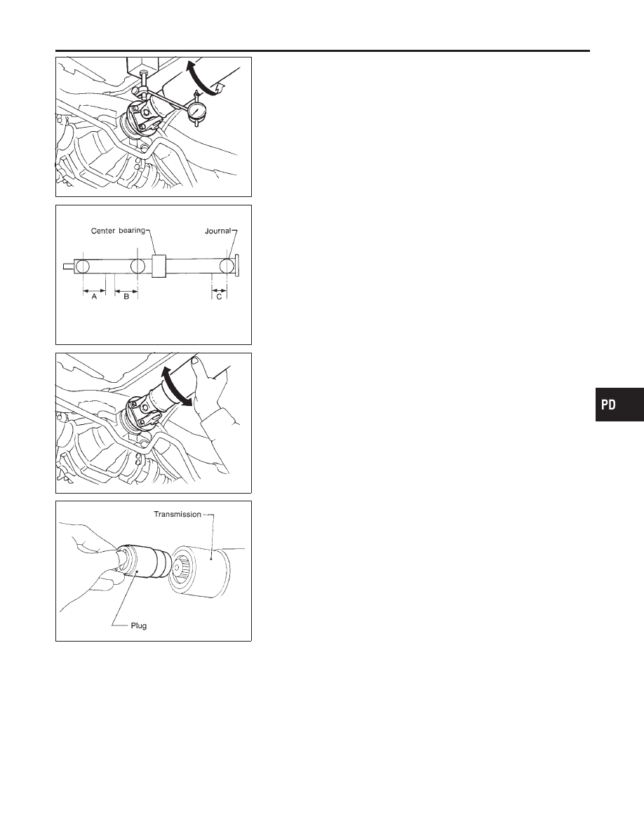
PROPELLER SHAFT VIBRATION

NMPD0003

If vibration is present at high speed, inspect propeller shaft runout
first.
1.

Raise rear wheels.

2.

Measure propeller shaft runout at indicated points by rotating
final drive companion flange with hands.

Runout limit: 0.6 mm (0.024 in)

SPD314A

SPD873

Propeller shaft runout measuring points:

Distance:

“A” 192 mm (7.56 in)
“B” 172 mm (6.77 in)
“C” 162 mm (6.38 in)

3.

If runout exceeds specifications, disconnect propeller shaft at
final drive companion flange. Then rotate companion flange
90, 180 or 270 degrees and reconnect propeller shaft.

Runout limit: 0.6 mm (0.024 in)

4.

Check runout again. If runout still exceeds specifications,
replace propeller shaft assembly.

5.

Perform road test.

APPEARANCE CHECKING

NMPD0004

I

Inspect propeller shaft tube surface for dents or cracks.
If damaged, replace propeller shaft assembly.

I

If center bearing is noisy or damaged, replace it.

SPD359

Removal and Installation

NMPD0005

I

Draw out propeller shaft from transmission and plug up rear
end of transmission rear extension housing.

GI

MA

EM

LC

EC

FE

CL

MT

AT

AX

SU

BR

ST

RS

BT

HA

SC

EL

IDX

PROPELLER SHAFT

On-vehicle Service (Cont’d)

PD-5

SPD526A

When installing the center bearing, use caution and pay attention
to the following procedures.

I

Install by aligning both matching marks on propeller shaft (put
on during removal) and on final drive companion flange.

I

Rotate bearing and make sure center bearing’s bearing cush-
ion connection part is always UP as shown in left figure.
And install it to vehicle by adjusting mounting bracket back-
forth position for not to give deflection of vehicle front to rear
direction to insulator.

CAUTION:

Align the arrow of the upper mounting bracket face the front
of the vehicle as shown in left figure.

SPD053A

If companion flange has been removed, put new alignment marks
B and C on it. Then reassemble using the following procedure.
Perform step 4 when final drive and propeller shaft are separated
from each other. Also perform step 4 when either of these parts is
replaced with a new one.

SPD062A

1.

Erase original marks B and C from companion flange with
suitable solvent.

2.

Mark (B)
A. Measure companion flange vertical runout.
B. Determine the position where maximum runout is read on
dial gauge. Put mark (shown by B in figure at left) on flange
perimeter corresponding to maximum runout position.

SPD063A

3.

Mark (C)
A. Measure companion flange surface runout.
B. Determine the position where maximum runout is read on
dial gauge. Put mark (shown by C in figure at left) on flange
perimeter corresponding to maximum runout position.

PROPELLER SHAFT

Removal and Installation (Cont’d)

PD-6

SPD061A

4.

Position companion flange and propeller shaft using alignment
marks A and B. Set the marks A and B as close to each other
as possible. Temporarily attach bolts and nuts.

5.

Press down propeller shaft with alignment mark C facing
upward. Then tighten the lower nut to specified torque.

6.

Tighten remaining nuts to specified torque.

SPD106

Inspection

NMPD0006

I

Inspect propeller shaft runout. If runout exceeds specifications,
replace propeller shaft assembly.

Runout limit: 0.6 mm (0.024 in)

SPD874

I

If the play exceeds specifications, replace propeller shaft
assembly.

Journal axial play:

0 mm (0 in) or less

SPD226A

Disassembly

NMPD0007

CENTER BEARING

NMPD0007S01

1.

Put matchmarks on flanges, and separate 2nd tube from 1st
tube.

2.

Put matchmarks on the flange and shaft.

SPD475A

3.

Remove locking nut with suitable tool.

4.

Remove companion flange with puller.

Tool number: HT72400000

GI

MA

EM

LC

EC

FE

CL

MT

AT

AX

SU

BR

ST

RS

BT

HA

SC

EL

IDX

PROPELLER SHAFT

Removal and Installation (Cont’d)

PD-7

SPD113

5.

Remove center bearing with Tool and press.

Tool number: ST30031000

SPD114

Assembly

NMPD0008

CENTER BEARING

NMPD0008S01

I

When installing center bearing, position the “F” mark on cen-
ter bearing toward rear of vehicle.

I

Apply a coat of grease to the end face of center bearing
and both sides of washer. Use multi-purpose lithium
grease that contains molybdenum disulfide.

SPD117

I

Stake the nut. Always use new one.

I

Align matchmarks when assembling tubes.

PROPELLER SHAFT

Disassembly (Cont’d)

PD-8


Content   ..  307  308  309  310   ..